Lenovo ThinkPad A31p ThinkPad A30/p, A31/p Hardware Maintenance Manual (Septem - Page 133
LCD panel, 2010 Front bezel
 |
View all Lenovo ThinkPad A31p manuals
Add to My Manuals
Save this manual to your list of manuals |
Page 133 highlights
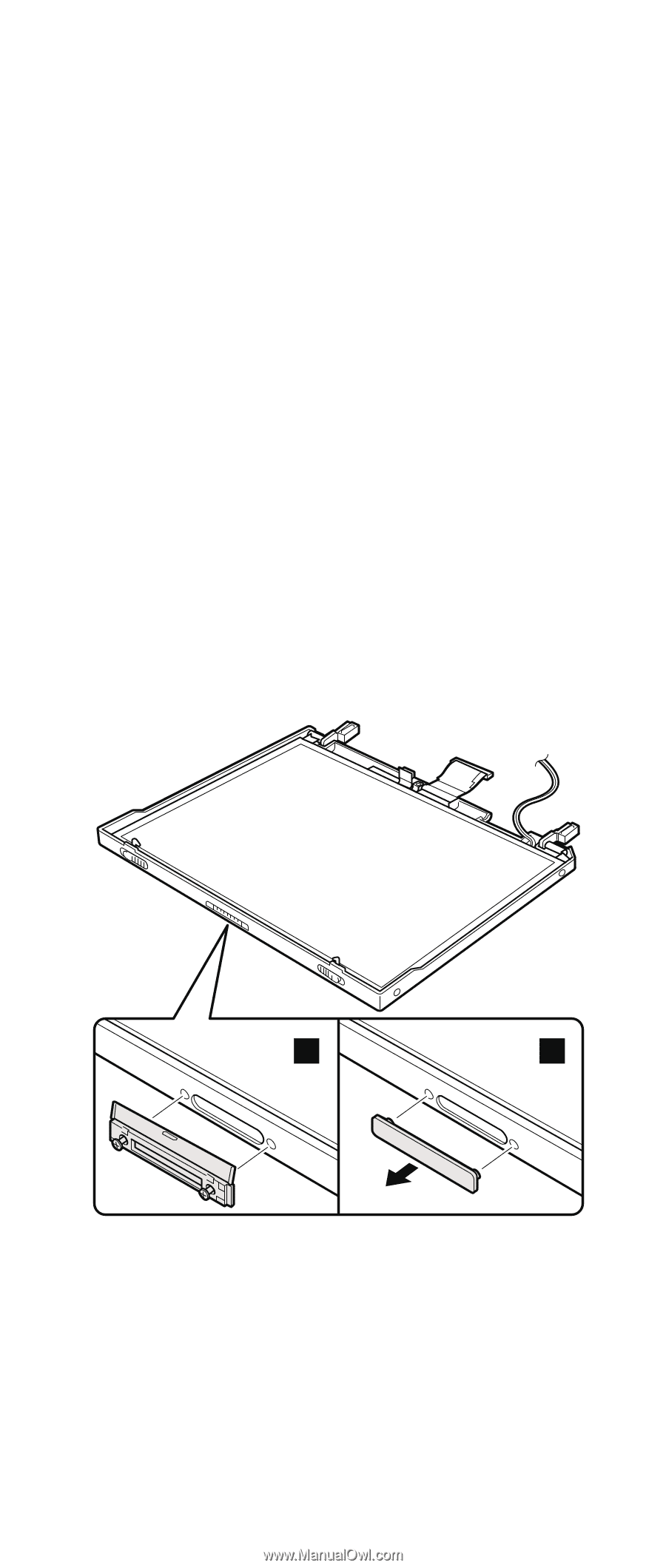
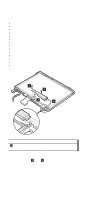
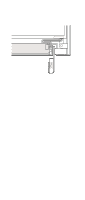
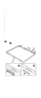
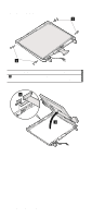
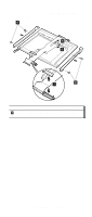
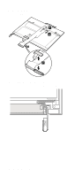
2030 LCD panel Removing and replacing a FRU For access, remove these FRUs, in order: v "1010 Battery pack" on page 64 v "1020 Mini PCI adapter" on page 65 v "1030 Communication daughter card (CDC)" on page 68 v "1040 Backup battery" on page 75 v "1060 Hard-disk drive" on page 77 v "1070 Ultrabay Plus device" on page 79 v "1080 Ultrabay 2000 device" on page 80 v "1100 Keyboard" on page 82 v "1110 Keyboard CRU insulator" on page 87 v "1120 Keyboard bezel" on page 89 v "1130 Hinge cover" on page 93 v "1160 Ultrabay Plus slot" on page 98 v "1200 LCD assembly" on page 110 v "2010 Front bezel" on page 125 v "2020 Inverter card" on page 127 Remove the UltraPort adapter if it has been screwed onto the LCD. To do this, remove the screws from the ends of the screw from both side of the adapter as shown in figure 1a . Remove the connector cover for the others as shown in figure 1b . 1a 1b (continued) ThinkPad A30, A30p, A31, A31p 129
-
 1
1 -
2
-
3
-
4
-
5
-
6
-
7
-
8
-
9
-
10
-
11
-
12
-
13
-
14
-
15
-
16
-
17
-
18
-
19
-
20
-
21
-
22
-
23
-
24
-
25
-
26
-
27
-
28
-
29
-
30
-
31
-
32
-
33
-
34
-
35
-
36
-
37
-
38
-
39
-
40
-
41
-
42
-
43
-
44
-
45
-
46
-
47
-
48
-
49
-
50
-
51
-
52
-
53
-
54
-
55
-
56
-
57
-
58
-
59
-
60
-
61
-
62
-
63
-
64
-
65
-
66
-
67
-
68
-
69
-
70
-
71
-
72
-
73
-
74
-
75
-
76
-
77
-
78
-
79
-
80
-
81
-
82
-
83
-
84
-
85
-
86
-
87
-
88
-
89
-
90
-
91
-
92
-
93
-
94
-
95
-
96
-
97
-
98
-
99
-
100
-
101
-
102
-
103
-
104
-
105
-
106
-
107
-
108
-
109
-
110
-
111
-
112
-
113
-
114
-
115
-
116
-
117
-
118
-
119
-
120
-
121
-
122
-
123
-
124
-
125
-
126
-
127
-
 128
128 -
 129
129 -
 130
130 -
 131
131 -
 132
132 -
 133
133 -
 134
134 -
 135
135 -
 136
136 -
 137
137 -
 138
138 -
139
-
140
-
141
-
142
-
143
-
144
-
145
-
146
-
147
-
148
-
149
-
150
-
151
-
152
-
153
-
154
-
155
-
156
-
157
-
158
-
159
-
160
-
161
-
162
-
163
-
164
-
165
-
166
-
167
-
168
-
169
-
170
-
171
-
172
-
173
-
174
-
175
-
176
-
177
-
178
-
179
-
180
-
181
-
182
-
183
-
184
-
185
-
186
-
187
-
188
-
189
-
190
-
191
-
192
 |
 |