Lenovo ThinkPad A31p ThinkPad A30/p, A31/p Hardware Maintenance Manual (Septem - Page 70
tab with your fingers., cable; it might snap. Unplug the jack by pulling
 |
View all Lenovo ThinkPad A31p manuals
Add to My Manuals
Save this manual to your list of manuals |
Page 70 highlights
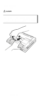
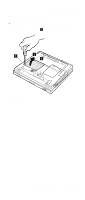
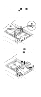
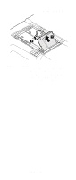
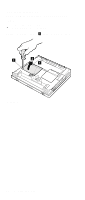
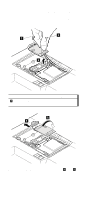
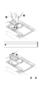
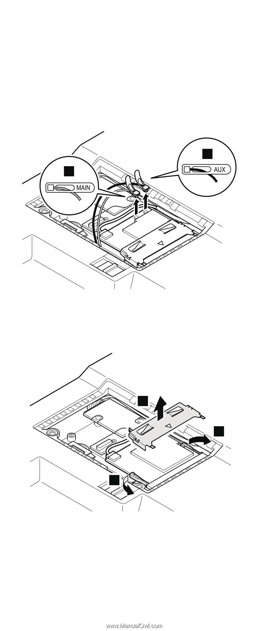
Removing and replacing a FRU The following illustrations show the wireless LAN/modem combo card. Antenna cables 3a and 3b are for the wireless LAN feature, and 6 is for the modem feature. This slot also supports a Mini PCI modem card. Note: When unplugging the antenna jack, do not pull the cable; it might snap. Unplug the jack by pulling a tab with your fingers. 3b 3a When installing: Plug the gray antenna cable with the tab marked "MAIN" ( 3a ) into jack J1, and the black antenna cable with the tab marked "AUX" ( 3b ) into jack J2. 4 5 5 (continued) 66 MT 2652/2653/2654
-
 1
1 -
2
-
3
-
4
-
5
-
6
-
7
-
8
-
9
-
10
-
11
-
12
-
13
-
14
-
15
-
16
-
17
-
18
-
19
-
20
-
21
-
22
-
23
-
24
-
25
-
26
-
27
-
28
-
29
-
30
-
31
-
32
-
33
-
34
-
35
-
36
-
37
-
38
-
39
-
40
-
41
-
42
-
43
-
44
-
45
-
46
-
47
-
48
-
49
-
50
-
51
-
52
-
53
-
54
-
55
-
56
-
57
-
58
-
59
-
60
-
61
-
62
-
63
-
64
-
 65
65 -
 66
66 -
 67
67 -
 68
68 -
 69
69 -
 70
70 -
 71
71 -
 72
72 -
 73
73 -
 74
74 -
 75
75 -
76
-
77
-
78
-
79
-
80
-
81
-
82
-
83
-
84
-
85
-
86
-
87
-
88
-
89
-
90
-
91
-
92
-
93
-
94
-
95
-
96
-
97
-
98
-
99
-
100
-
101
-
102
-
103
-
104
-
105
-
106
-
107
-
108
-
109
-
110
-
111
-
112
-
113
-
114
-
115
-
116
-
117
-
118
-
119
-
120
-
121
-
122
-
123
-
124
-
125
-
126
-
127
-
128
-
129
-
130
-
131
-
132
-
133
-
134
-
135
-
136
-
137
-
138
-
139
-
140
-
141
-
142
-
143
-
144
-
145
-
146
-
147
-
148
-
149
-
150
-
151
-
152
-
153
-
154
-
155
-
156
-
157
-
158
-
159
-
160
-
161
-
162
-
163
-
164
-
165
-
166
-
167
-
168
-
169
-
170
-
171
-
172
-
173
-
174
-
175
-
176
-
177
-
178
-
179
-
180
-
181
-
182
-
183
-
184
-
185
-
186
-
187
-
188
-
189
-
190
-
191
-
192
 |
 |
The following illustrations show the wireless LAN/modem
combo card. Antenna cables
±3a²
and
±3b²
are for the
wireless LAN feature, and
±6²
is for the modem feature.
This slot also supports a Mini PCI modem card.
Note:
When unplugging the antenna jack, do not pull the
cable; it might snap. Unplug the jack by pulling a
tab with your fingers.
3a
3b
When installing:
Plug the gray antenna cable with the tab
marked “MAIN” (
±3a²
) into jack
J1
, and
the black antenna cable with the tab
marked “AUX” (
±3b²
) into jack
J2
.
5
5
4
(continued)
Removing and replacing a FRU
66
MT 2652/2653/2654