Lenovo ThinkPad A31p ThinkPad A30/p, A31/p Hardware Maintenance Manual (Septem - Page 90
on the keyboard; to do so, try to slide the keyboard towards you. Do not push
 |
View all Lenovo ThinkPad A31p manuals
Add to My Manuals
Save this manual to your list of manuals |
Page 90 highlights
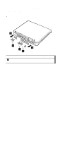
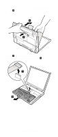
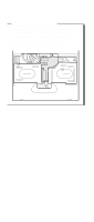
Removing and replacing a FRU 3. Press the keys indicated by arrows to latch the keyboard firmly in place. 4. To make sure that the front side of the keyboard is housed firmly, insert your fingers into the left and right slots of the Ultrabay; then, with your fingers in those slots, gently press the shift keys with your thumbs and try to slide the keyboard towards you. Do not push hard on parts (A) and (B) on the keyboard; to do so might distort the Ultrabay slots. (A) (B) 5. Replace the screws, using the new screws provided with the keyboard. 86 MT 2652/2653/2654
-
 1
1 -
2
-
3
-
4
-
5
-
6
-
7
-
8
-
9
-
10
-
11
-
12
-
13
-
14
-
15
-
16
-
17
-
18
-
19
-
20
-
21
-
22
-
23
-
24
-
25
-
26
-
27
-
28
-
29
-
30
-
31
-
32
-
33
-
34
-
35
-
36
-
37
-
38
-
39
-
40
-
41
-
42
-
43
-
44
-
45
-
46
-
47
-
48
-
49
-
50
-
51
-
52
-
53
-
54
-
55
-
56
-
57
-
58
-
59
-
60
-
61
-
62
-
63
-
64
-
65
-
66
-
67
-
68
-
69
-
70
-
71
-
72
-
73
-
74
-
75
-
76
-
77
-
78
-
79
-
80
-
81
-
82
-
83
-
84
-
 85
85 -
 86
86 -
 87
87 -
 88
88 -
 89
89 -
 90
90 -
 91
91 -
 92
92 -
 93
93 -
 94
94 -
 95
95 -
96
-
97
-
98
-
99
-
100
-
101
-
102
-
103
-
104
-
105
-
106
-
107
-
108
-
109
-
110
-
111
-
112
-
113
-
114
-
115
-
116
-
117
-
118
-
119
-
120
-
121
-
122
-
123
-
124
-
125
-
126
-
127
-
128
-
129
-
130
-
131
-
132
-
133
-
134
-
135
-
136
-
137
-
138
-
139
-
140
-
141
-
142
-
143
-
144
-
145
-
146
-
147
-
148
-
149
-
150
-
151
-
152
-
153
-
154
-
155
-
156
-
157
-
158
-
159
-
160
-
161
-
162
-
163
-
164
-
165
-
166
-
167
-
168
-
169
-
170
-
171
-
172
-
173
-
174
-
175
-
176
-
177
-
178
-
179
-
180
-
181
-
182
-
183
-
184
-
185
-
186
-
187
-
188
-
189
-
190
-
191
-
192
 |
 |
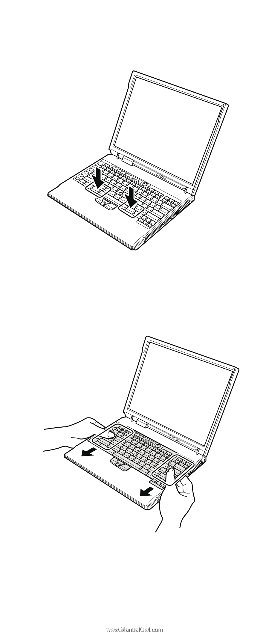
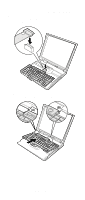
3.
Press the keys indicated by arrows to latch the
keyboard firmly in place.
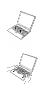
4.
To make sure that the front side of the keyboard is
housed firmly, insert your fingers into the left and right
slots of the Ultrabay; then, with your fingers in those
slots, gently press the shift keys with your thumbs and
try to slide the keyboard towards you. Do not push
hard on parts
(A)
and
(B)
on the keyboard; to do so
might distort the Ultrabay slots.
(A)
(B)
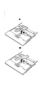
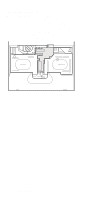
5.
Replace the screws, using the new screws provided
with the keyboard.
Removing and replacing a FRU
86
MT 2652/2653/2654