Lenovo ThinkPad L520 Hardware Maintenance Manual - Page 111
Antenna assembly, Removal steps of integrated camera, When installing
 |
View all Lenovo ThinkPad L520 manuals
Add to My Manuals
Save this manual to your list of manuals |
Page 111 highlights
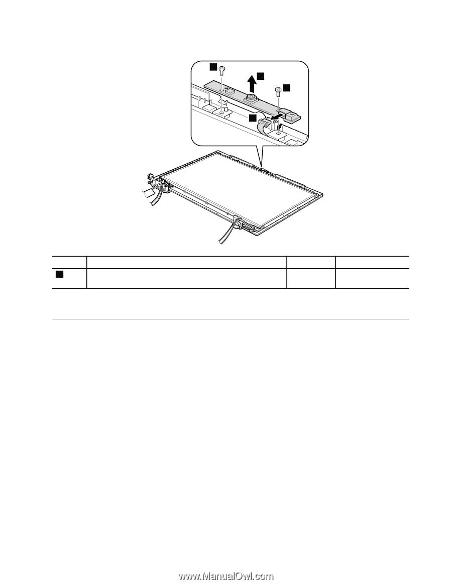
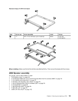
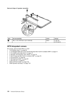
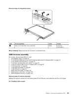
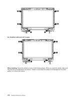
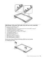
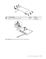
Removal steps of integrated camera 1 2 1 3 Step 1 Screw (quantity) M2 × 3 mm, flat-head, nylon-coated (2) Color Black Torque 0.181 Nm (1.85 kgfcm) When installing: Make sure that the connector is attached firmly. 2080 Antenna assembly For access, remove these FRUs in order: • "1010 Battery pack" on page 59 • "1110 Wireless WAN slot cover and PCI Express Mini Card for wireless WAN" on page 72 • "1110 mSATA solid state drive" on page 73 • "1120 Palm rest assembly with cables" on page 75 • "1130 PCI Express Mini Card for wireless LAN" on page 78 • "1170 Keyboard" on page 83 • "1180 Keyboard bezel" on page 85 • "1190 LCD unit" on page 87 • "2050 LCD front bezel" on page 102 • "2060 Speaker assembly" on page 103 • "2070 Integrated camera" on page 104 Removal steps of antenna assembly Release the antenna cables from the cable guides of the LCD rear cover assembly and from the hinges. For ThinkPad L520 models: Chapter 8. Removing and replacing a FRU 105
-
 1
1 -
2
-
3
-
4
-
5
-
6
-
7
-
8
-
9
-
10
-
11
-
12
-
13
-
14
-
15
-
16
-
17
-
18
-
19
-
20
-
21
-
22
-
23
-
24
-
25
-
26
-
27
-
28
-
29
-
30
-
31
-
32
-
33
-
34
-
35
-
36
-
37
-
38
-
39
-
40
-
41
-
42
-
43
-
44
-
45
-
46
-
47
-
48
-
49
-
50
-
51
-
52
-
53
-
54
-
55
-
56
-
57
-
58
-
59
-
60
-
61
-
62
-
63
-
64
-
65
-
66
-
67
-
68
-
69
-
70
-
71
-
72
-
73
-
74
-
75
-
76
-
77
-
78
-
79
-
80
-
81
-
82
-
83
-
84
-
85
-
86
-
87
-
88
-
89
-
90
-
91
-
92
-
93
-
94
-
95
-
96
-
97
-
98
-
99
-
100
-
101
-
102
-
103
-
104
-
105
-
 106
106 -
 107
107 -
 108
108 -
 109
109 -
 110
110 -
 111
111 -
 112
112 -
 113
113 -
 114
114 -
 115
115 -
 116
116 -
117
-
118
-
119
-
120
-
121
-
122
-
123
-
124
-
125
-
126
-
127
-
128
-
129
-
130
-
131
-
132
-
133
-
134
-
135
-
136
-
137
-
138
-
139
-
140
-
141
-
142
-
143
-
144
-
145
-
146
-
147
-
148
-
149
-
150
-
151
-
152
-
153
-
154
-
155
-
156
-
157
-
158
-
159
-
160
-
161
-
162
-
163
-
164
 |
 |