Lenovo ThinkPad L520 Hardware Maintenance Manual - Page 73
DIMM, 1070 Fan assembly, upper slot.
 |
View all Lenovo ThinkPad L520 manuals
Add to My Manuals
Save this manual to your list of manuals |
Page 73 highlights
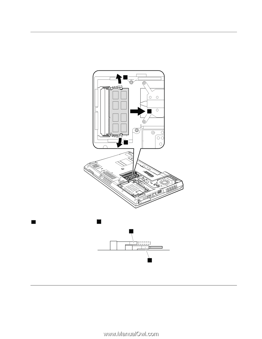
1060 DIMM For access, remove these FRUs in order: • "1010 Battery pack" on page 59 • "1040 Thermal cover" on page 63 Removal steps of DIMM 1 2 1 Note: If only one DIMM is used on the computer you are servicing, the card must be installed in SLOT-0 ( a : lower slot), but not in SLOT-1 ( b : upper slot). b a When installing: Insert the notched end of the DIMM into the socket. Press the DIMM firmly, and pivot it until it snaps into place. Make sure that it is firmly fixed in the slot and does not move easily. 1070 Fan assembly For access, remove these FRUs in order: • "1010 Battery pack" on page 59 • "1040 Thermal cover" on page 63 Chapter 8. Removing and replacing a FRU 67
-
 1
1 -
2
-
3
-
4
-
5
-
6
-
7
-
8
-
9
-
10
-
11
-
12
-
13
-
14
-
15
-
16
-
17
-
18
-
19
-
20
-
21
-
22
-
23
-
24
-
25
-
26
-
27
-
28
-
29
-
30
-
31
-
32
-
33
-
34
-
35
-
36
-
37
-
38
-
39
-
40
-
41
-
42
-
43
-
44
-
45
-
46
-
47
-
48
-
49
-
50
-
51
-
52
-
53
-
54
-
55
-
56
-
57
-
58
-
59
-
60
-
61
-
62
-
63
-
64
-
65
-
66
-
67
-
 68
68 -
 69
69 -
 70
70 -
 71
71 -
 72
72 -
 73
73 -
 74
74 -
 75
75 -
 76
76 -
 77
77 -
 78
78 -
79
-
80
-
81
-
82
-
83
-
84
-
85
-
86
-
87
-
88
-
89
-
90
-
91
-
92
-
93
-
94
-
95
-
96
-
97
-
98
-
99
-
100
-
101
-
102
-
103
-
104
-
105
-
106
-
107
-
108
-
109
-
110
-
111
-
112
-
113
-
114
-
115
-
116
-
117
-
118
-
119
-
120
-
121
-
122
-
123
-
124
-
125
-
126
-
127
-
128
-
129
-
130
-
131
-
132
-
133
-
134
-
135
-
136
-
137
-
138
-
139
-
140
-
141
-
142
-
143
-
144
-
145
-
146
-
147
-
148
-
149
-
150
-
151
-
152
-
153
-
154
-
155
-
156
-
157
-
158
-
159
-
160
-
161
-
162
-
163
-
164
 |
 |
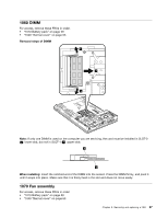
1060 DIMM
For access, remove these FRUs in order:
•
“1010 Battery pack” on page 59
•
“1040 Thermal cover” on page 63
Removal steps of DIMM
2
1
1
Note:
If only one DIMM is used on the computer you are servicing, the card must be installed in SLOT-0
(
a
: lower slot), but not in SLOT-1 (
b
: upper slot).
b
a
When installing:
Insert the notched end of the DIMM into the socket. Press the DIMM firmly, and pivot it
until it snaps into place. Make sure that it is firmly fixed in the slot and does not move easily.
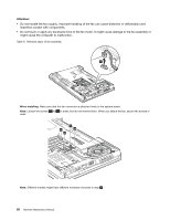
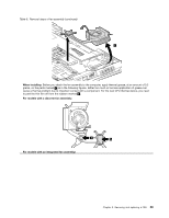
1070 Fan assembly
For access, remove these FRUs in order:
•
“1010 Battery pack” on page 59
•
“1040 Thermal cover” on page 63
Chapter 8
.
Removing and replacing a FRU
67