Lenovo ThinkPad L520 (English) User Guide - Page 131
Be sure to attach the red cable to the Main connector, and the blue cable to the AUX connector.
 |
View all Lenovo ThinkPad L520 manuals
Add to My Manuals
Save this manual to your list of manuals |
Page 131 highlights
6. Remove the screws and the card pops up. Remove the card. 7. Align the contact edge of the new PCI Express Mini Card with the corresponding socket. Pivot the card until you can snap it into place. Secure the card with the two screws. 8. Connect the antenna cables to the new PCI Express Mini Card as shown in the drawing. Note: Be sure to attach the red cable to the Main connector, and the blue cable to the AUX connector. Chapter 6. Replacing devices 113
-
 1
1 -
2
-
3
-
4
-
5
-
6
-
7
-
8
-
9
-
10
-
11
-
12
-
13
-
14
-
15
-
16
-
17
-
18
-
19
-
20
-
21
-
22
-
23
-
24
-
25
-
26
-
27
-
28
-
29
-
30
-
31
-
32
-
33
-
34
-
35
-
36
-
37
-
38
-
39
-
40
-
41
-
42
-
43
-
44
-
45
-
46
-
47
-
48
-
49
-
50
-
51
-
52
-
53
-
54
-
55
-
56
-
57
-
58
-
59
-
60
-
61
-
62
-
63
-
64
-
65
-
66
-
67
-
68
-
69
-
70
-
71
-
72
-
73
-
74
-
75
-
76
-
77
-
78
-
79
-
80
-
81
-
82
-
83
-
84
-
85
-
86
-
87
-
88
-
89
-
90
-
91
-
92
-
93
-
94
-
95
-
96
-
97
-
98
-
99
-
100
-
101
-
102
-
103
-
104
-
105
-
106
-
107
-
108
-
109
-
110
-
111
-
112
-
113
-
114
-
115
-
116
-
117
-
118
-
119
-
120
-
121
-
122
-
123
-
124
-
125
-
 126
126 -
 127
127 -
 128
128 -
 129
129 -
 130
130 -
 131
131 -
 132
132 -
 133
133 -
 134
134 -
 135
135 -
 136
136 -
137
-
138
-
139
-
140
-
141
-
142
-
143
-
144
-
145
-
146
-
147
-
148
-
149
-
150
-
151
-
152
-
153
-
154
-
155
-
156
-
157
-
158
-
159
-
160
-
161
-
162
-
163
-
164
-
165
-
166
-
167
-
168
-
169
-
170
-
171
-
172
-
173
-
174
-
175
-
176
-
177
-
178
-
179
-
180
-
181
-
182
-
183
-
184
-
185
-
186
-
187
-
188
-
189
-
190
-
191
-
192
-
193
-
194
-
195
-
196
-
197
-
198
-
199
-
200
-
201
-
202
-
203
-
204
-
205
-
206
-
207
-
208
-
209
-
210
-
211
-
212
-
213
-
214
-
215
-
216
-
217
-
218
-
219
-
220
-
221
-
222
-
223
-
224
-
225
 |
 |
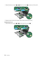
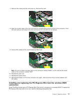
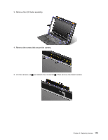
6. Remove the screws and the card pops up. Remove the card.
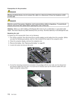
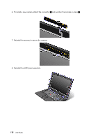
7. Align the contact edge of the new PCI Express Mini Card with the corresponding socket. Pivot the card
until you can snap it into place. Secure the card with the two screws.
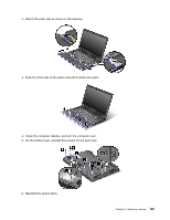
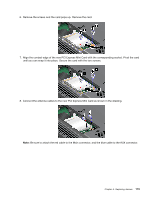
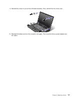
8. Connect the antenna cables to the new PCI Express Mini Card as shown in the drawing.
Note:
Be sure to attach the red cable to the Main connector, and the blue cable to the AUX connector.
Chapter 6
.
Replacing devices
113