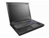
Lenovo ThinkPad W701 Hardware Maintenance Manual
Lenovo ThinkPad W701 Manual
 |
View all Lenovo ThinkPad W701 manuals
Add to My Manuals
Save this manual to your list of manuals |
Lenovo ThinkPad W701 manual content summary:
- Lenovo ThinkPad W701 | Hardware Maintenance Manual - Page 1
ThinkPad W700, W700ds, W701, and W701ds Hardware Maintenance Manual - Lenovo ThinkPad W701 | Hardware Maintenance Manual - Page 2
and the product it supports, be sure to read the general information under Appendix A "Notices" on page 209. Eighth Edition (June 2011) © Copyright Lenovo 2008, 2011. LIMITED AND RESTRICTED RIGHTS NOTICE: If data or services is delivered pursuant a General Services Administration "GSA" contract, use - Lenovo ThinkPad W701 | Hardware Maintenance Manual - Page 3
the backup battery 37 Chapter 4. Related service information 39 Restoring the factory contents by using Product Recovery discs 39 Restoring the factory contents by using Recovery Disc Set 39 Passwords 41 Power-on password 41 Hard-disk password 41 © Copyright Lenovo 2008, 2011 Supervisor - Lenovo ThinkPad W701 | Hardware Maintenance Manual - Page 4
) DVDs . . . 201 Windows Vista Business (64 bit) DVDs . . . 202 Windows Vista Ultimate (64 bit) DVDs . . . . 204 Windows 7 Professional (64 bit) DVDs. . . . 204 Common service tools 207 Appendix A. Notices 209 Trademarks 210 ii ThinkPad W700, W700ds, W701, and W701ds Hardware Maintenance Manual - Lenovo ThinkPad W701 | Hardware Maintenance Manual - Page 5
, 2758, 2762, and 2763 ThinkPad W701 and W701ds MT 2500, 2541, 2542, 2543, 2544, 4323, and 4326 Use this manual along with the advanced diagnostic tests to troubleshoot problems. Important: This manual is intended only for trained service technicians who are familiar with ThinkPad products. Use this - Lenovo ThinkPad W701 | Hardware Maintenance Manual - Page 6
iv ThinkPad W700, W700ds, W701, and W701ds Hardware Maintenance Manual - Lenovo ThinkPad W701 | Hardware Maintenance Manual - Page 7
presents following safety information that you need to be familiar with before you service a ThinkPad Notebook. • "General safety" on page 1 • "Electrical safety" on page 2 • "Safety inspection guide" on page 3 • "Handling devices that are sensitive to electrostatic discharge" on page 3 • "Grounding - Lenovo ThinkPad W701 | Hardware Maintenance Manual - Page 8
approved probe leads and accessories for that tester. - ; Instructions for Power supply units - Pumps - Blowers and fans - Motor generators - Similar units to listed above This practice ensures correct grounding of the units. 2 ThinkPad W700, W700ds, W701, and W701ds Hardware Maintenance Manual - Lenovo ThinkPad W701 | Hardware Maintenance Manual - Page 9
off power. - Send another person to get medical aid. Safety inspection guide The purpose of this inspection guide is to assist you in identifying potentially unsafe conditions. As each machine was designed and built, required safety items were installed to protect users and service technicians - Lenovo ThinkPad W701 | Hardware Maintenance Manual - Page 10
that meets the specific service requirement. Note: computers. Grounding requirements Electrical grounding of the computer is required for operator safety and correct system function. Proper grounding of the electrical outlet ThinkPad W700, W700ds, W701, and W701ds Hardware Maintenance Manual - Lenovo ThinkPad W701 | Hardware Maintenance Manual - Page 11
DANGER DANGER DANGER DANGER DANGER DANGER Chapter 1. Safety information 5 - Lenovo ThinkPad W701 | Hardware Maintenance Manual - Page 12
DANGER 6 ThinkPad W700, W700ds, W701, and W701ds Hardware Maintenance Manual - Lenovo ThinkPad W701 | Hardware Maintenance Manual - Page 13
PERIGO PERIGO PERIGO Chapter 1. Safety information 7 - Lenovo ThinkPad W701 | Hardware Maintenance Manual - Page 14
PERIGO PERIGO PERIGO PERIGO PERIGO 8 ThinkPad W700, W700ds, W701, and W701ds Hardware Maintenance Manual - Lenovo ThinkPad W701 | Hardware Maintenance Manual - Page 15
DANGER DANGER DANGER DANGER DANGER Chapter 1. Safety information 9 - Lenovo ThinkPad W701 | Hardware Maintenance Manual - Page 16
DANGER DANGER DANGER VORSICHT VORSICHT 10 ThinkPad W700, W700ds, W701, and W701ds Hardware Maintenance Manual - Lenovo ThinkPad W701 | Hardware Maintenance Manual - Page 17
VORSICHT VORSICHT VORSICHT VORSICHT VORSICHT VORSICHT Chapter 1. Safety information 11 - Lenovo ThinkPad W701 | Hardware Maintenance Manual - Page 18
12 ThinkPad W700, W700ds, W701, and W701ds Hardware Maintenance Manual - Lenovo ThinkPad W701 | Hardware Maintenance Manual - Page 19
Chapter 1. Safety information 13 - Lenovo ThinkPad W701 | Hardware Maintenance Manual - Page 20
14 ThinkPad W700, W700ds, W701, and W701ds Hardware Maintenance Manual - Lenovo ThinkPad W701 | Hardware Maintenance Manual - Page 21
Chapter 1. Safety information 15 - Lenovo ThinkPad W701 | Hardware Maintenance Manual - Page 22
16 ThinkPad W700, W700ds, W701, and W701ds Hardware Maintenance Manual - Lenovo ThinkPad W701 | Hardware Maintenance Manual - Page 23
Laser compliance statement (multilingual translations) The laser compliance statements in this section are provided in the following languages: • English • Arabic • Brazilian Portuguese Chapter 1. Safety information 17 - Lenovo ThinkPad W701 | Hardware Maintenance Manual - Page 24
• French • German • Hebrew • Japanese • Korean • Spanish • Traditional Chinese 18 ThinkPad W700, W700ds, W701, and W701ds Hardware Maintenance Manual - Lenovo ThinkPad W701 | Hardware Maintenance Manual - Page 25
Chapter 1. Safety information 19 - Lenovo ThinkPad W701 | Hardware Maintenance Manual - Page 26
20 ThinkPad W700, W700ds, W701, and W701ds Hardware Maintenance Manual - Lenovo ThinkPad W701 | Hardware Maintenance Manual - Page 27
Chapter 1. Safety information 21 - Lenovo ThinkPad W701 | Hardware Maintenance Manual - Page 28
22 ThinkPad W700, W700ds, W701, and W701ds Hardware Maintenance Manual - Lenovo ThinkPad W701 | Hardware Maintenance Manual - Page 29
Chapter 1. Safety information 23 - Lenovo ThinkPad W701 | Hardware Maintenance Manual - Page 30
24 ThinkPad W700, W700ds, W701, and W701ds Hardware Maintenance Manual - Lenovo ThinkPad W701 | Hardware Maintenance Manual - Page 31
lenovo.com/support. 2. Enter the product number of the computer or press Auto-detect button on the screen. 3. Select Downloads and drivers. 4. Follow the directions on the screen and install the necessary software. Use the following strategy to prevent unnecessary expense for replacing and servicing - Lenovo ThinkPad W701 | Hardware Maintenance Manual - Page 32
on the screen to diagnose computer you are servicing. Strategy for replacing FRUs for CTO, CMV, and GAV Product definition Dynamic Configure To Order (CTO) This provides the ability for a customer to configure an IBM® or a Lenovo ThinkPad W700, W700ds, W701, and W701ds Hardware Maintenance Manual - Lenovo ThinkPad W701 | Hardware Maintenance Manual - Page 33
(GAV) This is a standard model (fixed configuration). GAVs are announced and offered to all customers. the following Web site: http://www.lenovo.com/support/site.wss/document.do?lndocid=LOOK-WARNTY SERVICE PARTS. Under "Parts Information by Date" select SYSTEM SERVICE PARTS. The list of service - Lenovo ThinkPad W701 | Hardware Maintenance Manual - Page 34
28 ThinkPad W700, W700ds, W701, and W701ds Hardware Maintenance Manual - Lenovo ThinkPad W701 | Hardware Maintenance Manual - Page 35
Windows" on page 33 - "FRU tests" on page 33 • "Power system checkout" on page 35 The descriptions in this chapter apply to any ThinkPad model that supports the PC-Doctor® for DOS diagnostics program. Some descriptions might not apply to your particular computer. Before you go to the checkout guide - Lenovo ThinkPad W701 | Hardware Maintenance Manual - Page 36
following Web site: http://www.lenovo.com/support To create the PC-Doctor diagnostic CD, follow the instructions on the Web site. For some possible configurations of the computer, PC-Doctor might not run correctly. To avoid this problem, you need to initialize the computer setup by use of the BIOS - Lenovo ThinkPad W701 | Hardware Maintenance Manual - Page 37
Configuration utility for DOS. The utility is available on the following Web site: http://www.lenovo.com/support PC-Doctor cannot be used to test a device that is in the docking station, even if the computer supports the docking station the instructions on the screen. 8. The main panel of ThinkPad - Lenovo ThinkPad W701 | Hardware Maintenance Manual - Page 38
Events Log Utility • Run External Tests • Surface Scan Hard Disk • Benchmark System • DOS Shell • Tech Support Form • Battery Rundown • View Test Log • Print Log • Save Log • Full Erase Hard Drive • Quick Erase Hard Drive 32 ThinkPad W700, W700ds, W701, and W701ds Hardware Maintenance Manual - Lenovo ThinkPad W701 | Hardware Maintenance Manual - Page 39
In some models of ThinkPad Notebook, PC-Doctor for Windows enables you to troubleshoot and resolve problems related to the computer. Select one of the categories listed below to display symptoms and solutions: • Check System Health • System and Device Tests • Lenovo Troubleshooting Center • System - Lenovo ThinkPad W701 | Hardware Maintenance Manual - Page 40
test 1. Diagnostics ➙ CPU/Coprocessor. 2. Diagnostics ➙ Systemboard. 3. If the docking station or the port replicator is attached to the ThinkPad Notebook, detach it. 4. Place the computer on a horizontal surface, and run Diagnostics ➙ ThinkPad Devices ➙ HDD Active Protection Test. Note: Do not - Lenovo ThinkPad W701 | Hardware Maintenance Manual - Page 41
" on page 36 • "Checking the backup battery" on page 37 Checking the ac adapter You are here because the computer fails only when the ac adapter is used. • If the power problem occurs only when the ThinkPad W700 Mini Dock is used, replace the Mini Dock. • If the power-on indicator does not turn on - Lenovo ThinkPad W701 | Hardware Maintenance Manual - Page 42
than +11.0 V dc, measure the resistance between battery terminals 5 and 7. The resistance must be 4 to 30 K Ω. If the resistance is not correct, replace the battery pack. If the resistance is correct, replace the system board. 36 ThinkPad W700, W700ds, W701, and W701ds Hardware Maintenance Manual - Lenovo ThinkPad W701 | Hardware Maintenance Manual - Page 43
Checking the backup battery Do the following: 1. Power off the computer, and unplug the ac adapter from it. 2. Turn the computer upside down. 3. Remove the battery pack (see "1010 Battery pack" on page 68). 4. Remove the backup battery (see "1100 Backup battery" on page 82). 5. Measure the voltage - Lenovo ThinkPad W701 | Hardware Maintenance Manual - Page 44
38 ThinkPad W700, W700ds, W701, and W701ds Hardware Maintenance Manual - Lenovo ThinkPad W701 | Hardware Maintenance Manual - Page 45
. Follow the instructions on the screen to complete the Windows setup. Restoring the factory contents by using Recovery Disc Set When the hard disk drive (HDD) or solid state drive (SSD) is replaced because of a failure, no product recovery program is on the new drive. In this case, you must - Lenovo ThinkPad W701 | Hardware Maintenance Manual - Page 46
computer will restart into the Microsoft Windows desktop several times and you might experience periods when no activity is apparent on the screen for several minutes at a time. This is normal. 10. When the recovery process is complete, the Set Up Windows screen is displayed. Follow the instructions - Lenovo ThinkPad W701 | Hardware Maintenance Manual - Page 47
some device drivers. Passwords As many as three passwords may be needed for any ThinkPad Notebook: the power-on password (POP), the hard-disk password (HDP), and the supervisor password (SVP). If any of these passwords has been set, a prompt for it appears on the screen whenever the computer is - Lenovo ThinkPad W701 | Hardware Maintenance Manual - Page 48
Configuration window. Both user HDP and master HDP will have been removed. Power management To reduce power consumption, the computer has three power management modes: screen blank, sleep (standby in Windows XP), and hibernation. 42 ThinkPad W700, W700ds, W701, and W701ds Hardware Maintenance Manual - Lenovo ThinkPad W701 | Hardware Maintenance Manual - Page 49
display (keep current power plan) (in Windows XP, keep current power scheme). You can also put the computer into screen blank mode, press ThinkVantage button and use the ThinkVantage Productivity Center. Note: If the computer is a Windows 7 model, it does not support ThinkVantage Productivity Center - Lenovo ThinkPad W701 | Hardware Maintenance Manual - Page 50
set the mode to Hibernate when battery becomes low, and the battery charge becomes critically low. When the power is turned on, the computer returns from hibernation mode and resumes , go to "Intermittent problems" on page 51. 44 ThinkPad W700, W700ds, W701, and W701ds Hardware Maintenance Manual - Lenovo ThinkPad W701 | Hardware Maintenance Manual - Page 51
Note: For a device not supported by diagnostic codes in the ThinkPad Notebooks, see the manual for that device. Numeric error codes Table 2. Numeric error codes Symptom or error FRU or action, in sequence 0175 System board. Bad CRC1, stop POST - Lenovo ThinkPad W701 | Hardware Maintenance Manual - Page 52
8 hours by connecting the ac adapter. 2. Replace the backup battery and run BIOS Setup Utility to reset the time and date. 0252 Password checksum bad-The password is cleared. Reset the password by running BIOS Setup Utility. 46 ThinkPad W700, W700ds, W701, and W701ds Hardware Maintenance Manual - Lenovo ThinkPad W701 | Hardware Maintenance Manual - Page 53
Utility. 2. Replace the backup battery. 3. System board. 02F5 DMA test failed. 1. DIMM. 2. System board. 02F6 Software NMI failed 1. DIMM. 2. System board. 02F7 Fail-safe timer NMI failed 1. DIMM. 2. System board. 1801 Attached docking station is not supported Shut down the computer and - Lenovo ThinkPad W701 | Hardware Maintenance Manual - Page 54
configuration-Power docking station or port replicator if it is attached to the ThinkPad Notebook. 2. Place the ThinkPad Notebook on a horizontal surface. Do not apply any physical shock to the computer. 3. Run Diagnostics ➙ ThinkPad ThinkPad W700, W700ds, W701, and W701ds Hardware Maintenance Manual - Lenovo ThinkPad W701 | Hardware Maintenance Manual - Page 55
Load Setup Defaults in the BIOS Setup Utility. 2. Backup battery. 3. System board. 1. Restore the system configuration to what it was before the computer entered hibernation mode. 2. If memory size has been changed Utility and add the device in boot order. Chapter 4. Related service information 49 - Lenovo ThinkPad W701 | Hardware Maintenance Manual - Page 56
servicing has two or less visible defective pixels, it should not be considered faulty. However, if the LCD has three or more visible defective pixels, it will be deemed as defective by Lenovo and it should be replaced. Notes: 50 ThinkPad W700, W700ds, W701, and W701ds Hardware Maintenance Manual - Lenovo ThinkPad W701 | Hardware Maintenance Manual - Page 57
is operating correctly. (See "Power system checkout" on page 35.) 1. Turn off the computer. 2. Visually check each FRU for damage. Replace any damaged FRU. 3. Remove or disconnect all of the following devices: a. Non-ThinkPad devices b. Devices attached to the docking station or the port replicator - Lenovo ThinkPad W701 | Hardware Maintenance Manual - Page 58
does not recur, reconnect the removed devices one at a time until you find the failing FRU. 7. If the problem remains, replace the following FRUs one at a time (do not replace a nondefective FRU): a. System board b. LCD assembly 52 ThinkPad W700, W700ds, W701, and W701ds Hardware Maintenance Manual - Lenovo ThinkPad W701 | Hardware Maintenance Manual - Page 59
install and configure RAID, make sure of the current RAID setting on the computer you are servicing. ThinkPad W700, W700ds, W701, and W701ds supports either ROM Configuration Utility to create RAID volumes. To create RAID volumes, do as follows: 1. Turn on the computer. © Copyright Lenovo 2008, - Lenovo ThinkPad W701 | Hardware Maintenance Manual - Page 60
computer. 2. During the startup, when a prompt to press Ctrl+I to enter the Configuration Utility is displayed on the screen, press and hold the Ctrl key, and press the I key. 3. The screen of the computer you are servicing was set ThinkPad W700, W700ds, W701, and W701ds Hardware Maintenance Manual - Lenovo ThinkPad W701 | Hardware Maintenance Manual - Page 61
of the computer. 1 2 3 4 5 6 7 8 9 10 13 8 9 10 11 12 Table 7. Status indicators Indicator Meaning 1 Wireless LAN status Green: Blinking green: The wireless feature (802.11 standard) is on, and the radio link is ready for use. Data is being transmitted. © Copyright Lenovo 2008, 2011 55 - Lenovo ThinkPad W701 | Hardware Maintenance Manual - Page 62
green: or The Bluetooth wireless feature or battery is charged between 5% to 20% of the capacity, and being charged. The battery is charged between 0% to 5% of the capacity. The computer is connected to the ac power supply. 56 ThinkPad W700, W700ds, W701, and W701ds Hardware Maintenance Manual - Lenovo ThinkPad W701 | Hardware Maintenance Manual - Page 63
Blinking W700ds green: Turn off: 12 Fingerprint reader status only for W701 Green: and W701ds Blinking green: Blinking amber: 13 Color sensor status Green: Blinking green: The computer is in sleep (standby) mode. The computer is entering sleep (standby) mode or hibernation mode, or is - Lenovo ThinkPad W701 | Hardware Maintenance Manual - Page 64
58 ThinkPad W700, W700ds, W701, and W701ds Hardware Maintenance Manual - Lenovo ThinkPad W701 | Hardware Maintenance Manual - Page 65
Fn+F3 key combinations, you must have the ThinkPad PM device driver installed on the computer. • If you have logged on with an administrator user ID, and you press Fn+F3, the panel for selecting a power plan (power scheme) appears. If you have logged on with another user ID, and you press Fn+F3, the - Lenovo ThinkPad W701 | Hardware Maintenance Manual - Page 66
stops blinking. Moving the computer when it is entering hibernation may cause corruption of the hard disk drive. • To use this combination of the keys, you must have the ThinkPad PM device driver installed on the computer. 60 ThinkPad W700, W700ds, W701, and W701ds Hardware Maintenance Manual - Lenovo ThinkPad W701 | Hardware Maintenance Manual - Page 67
the ThinkLight® on or off. Note: This function is supported only on the ThinkPad computers that have the ThinkLight. The on or off status of the ThinkLight is shown on the screen for a few seconds when you press Fn+PgUp. Fn+Home The computer display becomes brighter. Fn+End The purpose of this - Lenovo ThinkPad W701 | Hardware Maintenance Manual - Page 68
62 ThinkPad W700, W700ds, W701, and W701ds Hardware Maintenance Manual - Lenovo ThinkPad W701 | Hardware Maintenance Manual - Page 69
replacing parts. Read this chapter carefully before replacing any FRU. Screw notices Loose screws can cause a reliability problem. In the ThinkPad Notebook, this problem firmly. • Ensure torque screw drivers are calibrated correctly following country specifications. © Copyright Lenovo 2008, 2011 63 - Lenovo ThinkPad W701 | Hardware Maintenance Manual - Page 70
by doing the following: 1. Install the LENOVO ThinkPad Hardware Maintenance Diskette Version 1.76 or later and restart the computer. 2. From the main menu, select 1. Set System Identification. 3. Select 1. Add S/N data from EEPROM. Follow the instructions on the screen. If the MTM and Product ID - Lenovo ThinkPad W701 | Hardware Maintenance Manual - Page 71
date, select 5. Read box build date from EEPROM, and follow the instruction on the screen. After an ECA has been applied to the machine, the EEPROM must be updated to reflect the ECA's application. Use the LENOVO ThinkPad Hardware Maintenance Diskette Version 1.76 or later to update the EEPROM. Note - Lenovo ThinkPad W701 | Hardware Maintenance Manual - Page 72
66 ThinkPad W700, W700ds, W701, and W701ds Hardware Maintenance Manual - Lenovo ThinkPad W701 | Hardware Maintenance Manual - Page 73
Important notice for servicing ThinkPad W700ds and W701ds The computer display is designed to be opened and used at an angle slightly greater than 90 degrees. Do not open the main display beyond 150 degrees. To do so might damage the computer hinge. Tips on using the dual screen model: • The second - Lenovo ThinkPad W701 | Hardware Maintenance Manual - Page 74
. A battery pack FRU should not be replaced unless this diagnostic shows that the battery is defective. The only exception to this is if the battery pack is physically damaged or a customer is reporting a possible safety issue. 68 ThinkPad W700, W700ds, W701, and W701ds Hardware Maintenance Manual - Lenovo ThinkPad W701 | Hardware Maintenance Manual - Page 75
. Note that a physically damaged battery pack is non-warranty replacement. DANGER Use only the battery specified in the parts list for your computer. Any other battery could ignite or explode. Table 9. Removal steps of battery pack 1 2 1020 Digitizer pen Table 10. Removal steps of digitizer pen - Lenovo ThinkPad W701 | Hardware Maintenance Manual - Page 76
. 1 2 3 1040 Hard disk drive (HDD) cover, HDD and HDD rubber rails or solid state drive (SSD) and storage converter For access, remove this FRU: • "1010 Battery pack" on page 68 Important: 70 ThinkPad W700, W700ds, W701, and W701ds Hardware Maintenance Manual - Lenovo ThinkPad W701 | Hardware Maintenance Manual - Page 77
all the information on it if possible. • Never remove the drive while the system is operating or is in suspend mode. • When replacing a hard disk drive in a RAID configured array, depending on which type of array is used, rebuilding the RAID array might be required. For more information, see Chapter - Lenovo ThinkPad W701 | Hardware Maintenance Manual - Page 78
: The rubber rails on the hard disk drive must be attached to the replacement drive. Otherwise the drive cannot be installed properly. SSD and storage converter: 5 6 1050 DIMM slot cover and DIMM For access, remove this FRU: 72 ThinkPad W700, W700ds, W701, and W701ds Hardware Maintenance Manual - Lenovo ThinkPad W701 | Hardware Maintenance Manual - Page 79
• "1010 Battery pack" on page 68 Table 13. Removal steps of DIMM slot cover and DIMM Note: Loosen the screws 1 , but do not remove them. 1 2 For ThinkPad W700 and W700ds: 3 3 4 Chapter 9. Removing and replacing a FRU 73 - Lenovo ThinkPad W701 | Hardware Maintenance Manual - Page 80
of DIMM slot cover and DIMM (continued) Note: If only one DIMM is used on the computer you are servicing, the card must be installed in SLOT-0 ( a ), but not in SLOT-1 ( b does not move easily. For ThinkPad W701 and W701ds: 3 4 3 74 ThinkPad W700, W700ds, W701, and W701ds Hardware Maintenance Manual - Lenovo ThinkPad W701 | Hardware Maintenance Manual - Page 81
you are servicing, the card must be installed in the lower slot of the slots under the keyboard. See "1120 DIMM slot cover and DIMM under keyboard for W701 and W701ds" on page 86. 1060 Palm rest or palm rest with fingerprint reader For access, remove these FRUs in order: • "1010 Battery pack" on - Lenovo ThinkPad W701 | Hardware Maintenance Manual - Page 82
Table 14. Removal steps of palm rest (continued) 2 3 3 5 4 When installing: When you attach the palm rest, do as follows: 76 ThinkPad W700, W700ds, W701, and W701ds Hardware Maintenance Manual - Lenovo ThinkPad W701 | Hardware Maintenance Manual - Page 83
2 firmly to the system board. Some models have only the fingerprint reader connector. 1 2 2. Attach the palm rest as shown in this figure. 3 3 Chapter 9. Removing and replacing a FRU 77 - Lenovo ThinkPad W701 | Hardware Maintenance Manual - Page 84
• "1010 Battery pack" on page 68 • "1020 Digitizer pen" on page 69 • "1040 Hard disk drive (HDD) cover, HDD and HDD rubber rails or solid state drive (SSD) and storage converter" on page 70 • "1060 Palm rest or palm rest with fingerprint reader" on page 75 78 ThinkPad W700, W700ds, W701, and W701ds - Lenovo ThinkPad W701 | Hardware Maintenance Manual - Page 85
. Removal steps of digitizer pen case assembly Step 1 Screw (quantity) M2 × 3.5 mm, wafer-head, nylon-coated (1) Color Silver Torque 0.181 Nm (1.85 kgfcm) 1080 Bluetooth daughter card (BDC-2.1) for W701 and W701ds For access, remove these FRUs in order: • "1010 Battery pack" on page 68 • "1040 - Lenovo ThinkPad W701 | Hardware Maintenance Manual - Page 86
Battery pack" on page 68 • "1040 Hard disk drive (HDD) cover, HDD and HDD rubber rails or solid state drive (SSD) and storage converter" on page 70 • "1060 Palm rest or palm rest with fingerprint reader" on page 75 Table 18. Removal steps of keyboard 1 80 ThinkPad W700, W700ds, W701, and W701ds - Lenovo ThinkPad W701 | Hardware Maintenance Manual - Page 87
Table 18. Removal steps of keyboard (continued) Step 1 Icon Screw (quantity) M2 × 17 mm, wafer-head, nylon-coated (1) Color Black Torque 0.181 Nm (1.85 kgfcm) Lift the sure that the keyboard edges a are under the frame as shown in this figure. a a Chapter 9. Removing and replacing a FRU 81 - Lenovo ThinkPad W701 | Hardware Maintenance Manual - Page 88
computer. Any other battery could ignite or explode. For access, remove these FRUs in order: • "1010 Battery pack battery For ThinkPad W700 and W700ds: 1 2 When installing: Make sure that the battery connector is attached firmly. 82 ThinkPad W700, W700ds, W701, and W701ds Hardware Maintenance Manual - Lenovo ThinkPad W701 | Hardware Maintenance Manual - Page 89
Table 19. Removal steps of backup battery (continued) For ThinkPad W701 and W701ds: 1 2 When installing: Make sure that the battery connector is attached firmly. 1110 Numeric keypad For access, remove these FRUs in order: • "1010 Battery pack" on page 68 • "1040 Hard disk drive (HDD) cover, HDD and - Lenovo ThinkPad W701 | Hardware Maintenance Manual - Page 90
Table 20. Removal steps of numeric keypad 2 1 Step 1 Screw (quantity) M2 × 3.5 mm, wafer-head, nylon-coated (1) Slide the keypad a little in the direction shown by arrow 3 . Color Silver Torque 0.181 Nm (1.85 kgfcm) 3 84 ThinkPad W700, W700ds, W701, and W701ds Hardware Maintenance Manual - Lenovo ThinkPad W701 | Hardware Maintenance Manual - Page 91
Table 20. Removal steps of numeric keypad (continued) 4 When installing: Make sure that the keypad edges 1 are under the frame as shown in this figure. 1 1 Chapter 9. Removing and replacing a FRU 85 - Lenovo ThinkPad W701 | Hardware Maintenance Manual - Page 92
ThinkPad W701 and W701ds, make sure that the cable 3 is under the frame as shown in this figure. 3 1120 DIMM slot cover and DIMM under keyboard for W701 and W701ds For access, remove this FRU: • "1010 Battery Keyboard" on page 80 86 ThinkPad W700, W700ds, W701, and W701ds Hardware Maintenance Manual - Lenovo ThinkPad W701 | Hardware Maintenance Manual - Page 93
Table 21. Removal steps of DIMM slot cover and DIMM under keyboard Note: Loosen the screw 1 , but do not remove it. 1 2 1 2 1 Chapter 9. Removing and replacing a FRU 87 - Lenovo ThinkPad W701 | Hardware Maintenance Manual - Page 94
on the computer you are servicing, the in order: • "1010 Battery pack" on page 68 ThinkPad W700 and W700ds: 1 1 1 1 1 Step 1 Screw (quantity) M2.5 × 9 mm, wafer-head, nylon-coated (5) Color Black Torque 0.392 Nm (4 kgfcm) 88 ThinkPad W700, W700ds, W701, and W701ds Hardware Maintenance Manual - Lenovo ThinkPad W701 | Hardware Maintenance Manual - Page 95
Table 22. Removal steps of keyboard bezel for W700 and W700ds (continued) 2 4 3 4 3 When installing: Make sure that all the claws are attached firmly. When installing: Make sure that the connector cable is routed as shown in this figure. Chapter 9. Removing and replacing a FRU 89 - Lenovo ThinkPad W701 | Hardware Maintenance Manual - Page 96
steps of keyboard bezel for W701 and W701ds For ThinkPad W701 and W701ds: 1 1 1 1 Torque 0.181 Nm (1.85 kgfcm) Step 1 Screw (quantity) M2.5 × 9 mm, wafer-head, nylon-coated (4) Color Black Torque 0.392 Nm (4 kgfcm) 90 ThinkPad W700, W700ds, W701, and W701ds Hardware Maintenance Manual - Lenovo ThinkPad W701 | Hardware Maintenance Manual - Page 97
Table 24. Removal steps of keyboard bezel for W701 and W701ds (continued) Note: Loosen the screws 2 , but do not remove them. 2 2 3 Chapter 9. Removing and replacing a FRU 91 - Lenovo ThinkPad W701 | Hardware Maintenance Manual - Page 98
attached firmly. When installing: Make sure that the connector cable is routed as shown in this figure. Table 25. Removal steps of speaker assembly for W701 and W701ds 1 1 1 2 Step Screw (quantity) Color 92 ThinkPad W700, W700ds, W701, and W701ds Hardware Maintenance Manual Torque - Lenovo ThinkPad W701 | Hardware Maintenance Manual - Page 99
of speaker assembly for W701 and W701ds (continued) 1 M2 the full-size PCI Express Mini Card slot. In this case, you also need FRUs listed in the following table. FRU 45N6044 For access, remove these FRUs in order: • "1010 Battery pack" on page 68 • "1040 Hard disk drive (HDD) replacing a FRU 93 - Lenovo ThinkPad W701 | Hardware Maintenance Manual - Page 100
Mini Card for wireless LAN/WiMAX For access, remove these FRUs in order: • "1010 Battery pack" on page 68 • "1040 Hard disk drive (HDD) cover, HDD and HDD rubber rails or solid state drive (SSD) and storage converter" on page 70 94 ThinkPad W700, W700ds, W701, and W701ds Hardware Maintenance Manual - Lenovo ThinkPad W701 | Hardware Maintenance Manual - Page 101
1120 DIMM slot cover and DIMM under keyboard for W701 and W701ds" on page 86 • "1130 Keyboard bezel and speaker assembly" on page 88 Table 27. Removal steps of PCI Express Mini Card for wireless LAN/WiMAX for W700 and W700ds For ThinkPad replacing a FRU 95 - Lenovo ThinkPad W701 | Hardware Maintenance Manual - Page 102
and the black cable into the jack labeled AUX on the card. If the computer you are servicing has three cables, put the white cable in the cable holder and place it , nylon-coated (2) 3 Color Black Torque 0.181 Nm (1.85 kgfcm) 96 ThinkPad W700, W700ds, W701, and W701ds Hardware Maintenance Manual - Lenovo ThinkPad W701 | Hardware Maintenance Manual - Page 103
ThinkPad W701 and W701ds (continued) When installing: • In models with wireless LAN card that has two antenna connectors, plug the gray cable into the jack labeled MAIN, and the black cable into the jack labeled AUX on the card. If the computer you are servicing "1010 Battery pack" replacing a FRU 97 - Lenovo ThinkPad W701 | Hardware Maintenance Manual - Page 104
× 3 mm, thin-head, nylon-coated (2) Color Silver Torque 0.181 Nm (1.85 kgfcm) 3 4 1170 CPU thermal device/fan For access, remove these FRUs in order: • "1010 Battery pack" on page 68 98 ThinkPad W700, W700ds, W701, and W701ds Hardware Maintenance Manual - Lenovo ThinkPad W701 | Hardware Maintenance Manual - Page 105
• "1120 DIMM slot cover and DIMM under keyboard for W701 and W701ds" on page 86 • "1130 Keyboard bezel and speaker assembly " on page 88 Table 30. Removal steps of CPU thermal device/fan for W700 and W700ds For ThinkPad replacing a FRU 99 - Lenovo ThinkPad W701 | Hardware Maintenance Manual - Page 106
the computer, problem due to imperfect contact with a component. For the new CPU thermal device/fan, you need to peel the thin film off from the rubber marked a . a b • Make sure that the fan connector is attached firmly. 100 ThinkPad W700, W700ds, W701, and W701ds Hardware Maintenance Manual - Lenovo ThinkPad W701 | Hardware Maintenance Manual - Page 107
Table 32. Removal steps of CPU thermal device/fan for W701 and W701ds For ThinkPad W701 and W701ds: Note: Loosen the screws 1 , 2 , and 3 , but do not remove them. When you can cause distortion or deformation and imperfect contact with components. 5 4 Chapter 9. Removing and replacing a FRU 101 - Lenovo ThinkPad W701 | Hardware Maintenance Manual - Page 108
or too less application of grease can cause a thermal problem due to imperfect contact with a component. a • Make sure that the fan connector is attached firmly. 1180 VGA thermal device/fan and thermal putty Note: In ThinkPad W701 and W701ds, thermal putty is used between the thermal device/fan and - Lenovo ThinkPad W701 | Hardware Maintenance Manual - Page 109
34. Removal steps of VGA thermal device/fan (continued) 2 3 4 1 For ThinkPad W700ds and W701ds: 5 6 7 Attention: Do not handle the fan roughly. Improper handling of the fan can cause distortion or deformation and imperfect contact with components. Chapter 9. Removing and replacing a FRU 103 - Lenovo ThinkPad W701 | Hardware Maintenance Manual - Page 110
a thermal problem due to imperfect contact with a component. For the new VGA thermal device/fan, you need to peel the thin films off from the rubbers marked a . a b a • Make sure that the fan connector is attached firmly. 104 ThinkPad W700, W700ds, W701, and W701ds Hardware Maintenance Manual - Lenovo ThinkPad W701 | Hardware Maintenance Manual - Page 111
ThinkPad W701 and W701ds When installing: • Before you attach the fan assembly to the computer problem due to imperfect contact with a component. b • Make sure that the fan connector is attached firmly. 1190 CPU For access, remove these FRUs in order: • "1010 Battery keyboard for W701 and W701ds" on - Lenovo ThinkPad W701 | Hardware Maintenance Manual - Page 112
for MXM NB9E GLM3 FRUs need to be replaced simultaneously FRU System board Base cover assembly Structure Frame model 45N6098 For access, remove these FRUs in order: • "1010 Battery pack" on page 68 • "1040 Hard disk drive (HDD) ThinkPad W700, W700ds, W701, and W701ds Hardware Maintenance Manual - Lenovo ThinkPad W701 | Hardware Maintenance Manual - Page 113
• "1120 DIMM slot cover and DIMM under keyboard for W701 and W701ds" on page 86 • "1130 Keyboard bezel and speaker assembly" on page 88 kgfcm) 3 When installing: Before you attach the video card to the computer, you need to peel the thin film off from the rubber marked a . Chapter 9. Removing and - Lenovo ThinkPad W701 | Hardware Maintenance Manual - Page 114
For access, remove these FRUs in order: • "1010 Battery pack" on page 68 • "1040 Hard disk drive ThinkPad W700 and W700ds: For models with 34-mm ExpressCard/54-mm ExpressCard slot: 1 1 2 Step Screw (quantity) Color Torque 108 ThinkPad W700, W700ds, W701, and W701ds Hardware Maintenance Manual - Lenovo ThinkPad W701 | Hardware Maintenance Manual - Page 115
, nylon-coated (1) For models with 34-mm ExpressCard/CompactFlash Card slot: Color Silver Silver Torque 0.181 Nm (1.85 kgfcm) 0.392 Nm (4 kgfcm) Chapter 9. Removing and replacing a FRU 109 - Lenovo ThinkPad W701 | Hardware Maintenance Manual - Page 116
3 Color Silver Silver Torque 0.181 Nm (1.85 kgfcm) 0.392 Nm (4 kgfcm) Table 40. Removal steps of HDD I/O sub card for W701 and W701ds For ThinkPad W701 and W701ds: For models with 34-mm ExpressCard/54-mm ExpressCard slot: 110 ThinkPad W700, W700ds, W701, and W701ds Hardware Maintenance Manual - Lenovo ThinkPad W701 | Hardware Maintenance Manual - Page 117
Table 40. Removal steps of HDD I/O sub card for W701 and W701ds (continued) 2 1 1 3 Step 1 2 3 Screw (quantity) M2 × 14 mm, small-head, nylon-coated (2) M2 × 3.5 mm, small-head, nylon- Torque 0.181 Nm (1.85 kgfcm) 0.181 Nm (1.85 kgfcm) 0.392 Nm (4 kgfcm) Chapter 9. Removing and replacing a FRU 111 - Lenovo ThinkPad W701 | Hardware Maintenance Manual - Page 118
Table 40. Removal steps of HDD I/O sub card for W701 and W701ds (continued) Step Screw (quantity) Color 1 M2 × 14 mm, small-head, nylon-coated (2) Silver 2 0.181 Nm (1.85 kgfcm) 0.181 Nm (1.85 kgfcm) 0.392 Nm (4 kgfcm) 112 ThinkPad W700, W700ds, W701, and W701ds Hardware Maintenance Manual - Lenovo ThinkPad W701 | Hardware Maintenance Manual - Page 119
Battery pack" on page 68 • "1040 Hard disk drive (HDD) cover, HDD and HDD rubber rails or solid state drive (SSD) and storage converter" on page 70 • "1060 Palm rest or palm rest with fingerprint reader" on page 75 • "1080 Bluetooth daughter card (BDC-2.1) for W701 and W701ds For ThinkPad W700 and - Lenovo ThinkPad W701 | Hardware Maintenance Manual - Page 120
M2 × 10 mm, wafer-head, nylon-coated (2) Step 6a is only for ThinkPad W700ds. Color Black Black Torque 0.392 Nm (4 kgfcm) 0.181 Nm (1.85 kgfcm) 6 6 6 6a When installing: In ThinkPad W700ds, make sure that the cable connector 6a is attached firmly. 114 ThinkPad W700, W700ds, W701, and W701ds - Lenovo ThinkPad W701 | Hardware Maintenance Manual - Page 121
: 1. Route the antenna cables along the cable guides and secure them with the tapes. As you guides, or a wire to be broken. 2. Make sure that the LCD connector is attached firmly. Table 42. Removal steps of LCD unit for W701 and W701ds For ThinkPad W701 and W701ds: Chapter 9. Removing and replacing - Lenovo ThinkPad W701 | Hardware Maintenance Manual - Page 122
Table 42. Removal steps of LCD unit for W701 and W701ds (continued) 1 1 2 2 Step 1 2 Screw cap - Screw (quantity) M2.5 × 9 mm, wafer-head, nylon- mm, wafer-head, nylon-coated (1) Color Silver Torque 0.181 Nm (1.85 kgfcm) 116 ThinkPad W700, W700ds, W701, and W701ds Hardware Maintenance Manual - Lenovo ThinkPad W701 | Hardware Maintenance Manual - Page 123
Table 42. Removal steps of LCD unit for W701 and W701ds (continued) 5 5 6 7 6 5 5 Step 5 6 Screw (quantity) M2.5 × 9 mm, wafer-head, nylon-coated (4) M2 × 12 mm, wafer-head, nylon-coated (2) Step 9a is only for ThinkPad W701ds. Color Black Black Torque 0.392 Nm (4 kgfcm) 0.181 Nm (1.85 - Lenovo ThinkPad W701 | Hardware Maintenance Manual - Page 124
page 93 • "1150 PCI Express Mini Card for wireless LAN/WiMAX" on page 94 • "1220 LCD unit and LCD cable cap" on page 113 118 ThinkPad W700, W700ds, W701, and W701ds Hardware Maintenance Manual - Lenovo ThinkPad W701 | Hardware Maintenance Manual - Page 125
× 3.5 mm, wafer-head, nylon-coated (1) Color Silver Torque 0.392 Nm ( 4 kgfcm) Color Silver Silver Torque 0.392 Nm (4 kgfcm) 0.181 Nm (1.85 kgfcm) Chapter 9. Removing and replacing a FRU 119 - Lenovo ThinkPad W701 | Hardware Maintenance Manual - Page 126
is only for ThinkPad W700 and W700ds. Step Screw (quantity) 4 M2 × 10 mm, wafer-head, nylon-coated (4) 4a M2 × 10 mm, wafer-head, nylon-coated (2) Color Black Black Torque 0.181 Nm (1.85 kgfcm) 0.181 Nm (1.85 kgfcm) 7 120 ThinkPad W700, W700ds, W701, and W701ds Hardware Maintenance Manual - Lenovo ThinkPad W701 | Hardware Maintenance Manual - Page 127
1240 ODD switch sub card for W700 and W700ds For access, remove these FRUs, in order: • "1010 Battery pack" on page 68 • "1040 Hard disk drive (HDD) cover, HDD and HDD rubber rails or solid board and the card is routed firmly as shown in this figure. Chapter 9. Removing and replacing a FRU 121 - Lenovo ThinkPad W701 | Hardware Maintenance Manual - Page 128
. Removal steps of audio and card reader I/O card 1 Step 1 Screw (quantity) M2 × 3.5 mm, wafer-head, nylon-coated (1) Color Silver Torque 0.181 Nm (1.85 kgfcm) 122 ThinkPad W700, W700ds, W701, and W701ds Hardware Maintenance Manual - Lenovo ThinkPad W701 | Hardware Maintenance Manual - Page 129
board for MXM-support, with TPM for W700 42W8201 System board for MXM-support, non-TPM for W700 FRUs need to be replaced simultaneously FRU G-forces. Note: Dropping a system board from a height of as little as 6 inches so that it falls flat on a hard bench can subject the accelerometer to as much - Lenovo ThinkPad W701 | Hardware Maintenance Manual - Page 130
2. Run Diagnostics ➙ ThinkPad Devices ➙ HDD Active Protection Test. Attention: Do not apply physical shock to the computer while the test is running. Important notices for RAID setting: Before you replace the system board, make sure that you read Chapter 5 "Installing and configuring RAID" on page - Lenovo ThinkPad W701 | Hardware Maintenance Manual - Page 131
. When you service the system board, avoid any kind of rough handling. For ThinkPad W701 and W701ds: a PCH (Platform Controller Hub) b CPU c Video sub card (Mobile PCI Express Module) d Accelerometer chip for the HDD Active Protection System Chapter 9. Removing and replacing a FRU 125 - Lenovo ThinkPad W701 | Hardware Maintenance Manual - Page 132
Upper side of the system board: a b c Bottom side of the system board: d 126 ThinkPad W700, W700ds, W701, and W701ds Hardware Maintenance Manual - Lenovo ThinkPad W701 | Hardware Maintenance Manual - Page 133
of the PC Card/Express Card slot assembly or PC Card/Smart Card slots assembly is attached to the system board firmly. Chapter 9. Removing and replacing a FRU 127 - Lenovo ThinkPad W701 | Hardware Maintenance Manual - Page 134
labels of several kinds. When you replace the base cover, you need to Serial number label 2 Wireless LAN LMA label 3 Windows license label (COA) 4 Wireless LAN label 5 ThinkPad W700 and W700ds: 1 2 7 6 3 5 4 128 ThinkPad W700, W700ds, W701, and W701ds Hardware Maintenance Manual - Lenovo ThinkPad W701 | Hardware Maintenance Manual - Page 135
For the location of each label, refer the following figure: For ThinkPad W701 and W701ds: 1 2 7 6 3 5 4 2010 LCD front bezel (LCD cover kit) For access, remove this FRU: • "1010 Battery pack" on page 68 Table 47. Removal steps of LCD front bezel 1 1 1 1 1 1 Step 1 Screw cap Screw ( - Lenovo ThinkPad W701 | Hardware Maintenance Manual - Page 136
card For access, remove these FRUs in order: • "1010 Battery pack" on page 68 • "2010 LCD front bezel (LCD cover kit)" on page 129 Table 48. Removal steps of inverter card for W700 and W700ds For ThinkPad W700 and W700ds: 130 ThinkPad W700, W700ds, W701, and W701ds Hardware Maintenance Manual - Lenovo ThinkPad W701 | Hardware Maintenance Manual - Page 137
cable and white cable a and the connector that has blue cable and white cable b are attached firmly. Table 49. Removal steps of inverter card for W701 and W701ds For ThinkPad W701 and W701ds: Chapter 9. Removing and replacing a FRU 131 - Lenovo ThinkPad W701 | Hardware Maintenance Manual - Page 138
the connectors are attached firmly. 2030 Integrated camera For access, remove these FRUs in order: • "1010 Battery pack" on page 68 • "2010 LCD front bezel (LCD cover kit)" on page 129 Color Black Torque 0.181 Nm (1.85 kgfcm) 132 ThinkPad W700, W700ds, W701, and W701ds Hardware Maintenance Manual - Lenovo ThinkPad W701 | Hardware Maintenance Manual - Page 139
Table 50. Removal steps of integrated camera 1 When installing: Make sure that the connector is attached firmly. 2 2 3 Step 1 Screw (quantity) M2 × 3.5 mm, thin-head, nylon-coated (2) Color Black Torque 0.181 Nm (1.85 kgfcm) Chapter 9. Removing and replacing a FRU 133 - Lenovo ThinkPad W701 | Hardware Maintenance Manual - Page 140
2040 Bluetooth daughter card (BDC-2.1) for W700 and W700ds For access, remove these FRUs in order: • "1010 Battery pack" on page 68 • "2010 LCD front bezel (LCD cover kit)" on on page 130 • "2030 Integrated camera" on page 132 134 ThinkPad W700, W700ds, W701, and W701ds Hardware Maintenance Manual - Lenovo ThinkPad W701 | Hardware Maintenance Manual - Page 141
• "2040 Bluetooth daughter card (BDC-2.1) for W700 and W700ds" on page 134 Table 52. Removal steps of LCD panel, hinges, and LCD cable Step 1 to 5 is only for ThinkPad W700 and W700ds. 1 2 3 3 Chapter 9. Removing and replacing a FRU 135 - Lenovo ThinkPad W701 | Hardware Maintenance Manual - Page 142
(4) Color Silver Black When installing: Make sure that the connector is attached firmly. For ThinkPad W700 and W701: 6 6 6 7 6 6 6 Torque 0.392 Nm (4 kgfcm) 0.392 Nm (4 kgfcm) Step Screw (quantity) Color 136 ThinkPad W700, W700ds, W701, and W701ds Hardware Maintenance Manual Torque - Lenovo ThinkPad W701 | Hardware Maintenance Manual - Page 143
(4 kgfcm) 8 9 8 8 Step 8 Screw (quantity) M2 × 3 mm, wafer-head, nylon-coated (6) Color Black For ThinkPad W700 and W701, skip steps from 10 and 11 . For ThinkPad W700ds and W701ds: 6 6 6 8 6 7 7 6 7 Torque 0.181 Nm (1.85 kgfcm) Step 6 7 Screw (quantity) M2.5 × 7 mm, wafer-head, nylon - Lenovo ThinkPad W701 | Hardware Maintenance Manual - Page 144
head, nylon-coated (6) 10 11 9 10 Color Black Torque 0.181 Nm (1.85 kgfcm) 12 13 When installing: Make sure that the LCD cable is attached firmly. 2060 Second LCD bezel (second LCD cover kit) (for ThinkPad W700ds and W701ds) For access, remove these FRUs in order: • "1010 Battery pack" on page - Lenovo ThinkPad W701 | Hardware Maintenance Manual - Page 145
" on page 130 • "2030 Integrated camera" on page 132 • "2040 Bluetooth daughter card (BDC-2.1) for W700 and W700ds" on page 134 • "2050 page 134 Table 53. Removal steps of second LCD bezel (second LCD cover kit) (for ThinkPad W700ds and W701ds) 2 2 2 2 2 2 Step 2 Screw (quantity) M2.5 × 4.5 mm, - Lenovo ThinkPad W701 | Hardware Maintenance Manual - Page 146
132 • "2040 Bluetooth daughter card (BDC-2.1) for W700 and W700ds" on page 134 • "2050 LCD panel, hinges, and LCD cable" on page 134 • "2060 Second LCD bezel (second LCD cover kit) (for ThinkPad W700ds and W701ds)" on page 138 140 ThinkPad W700, W700ds, W701, and W701ds Hardware Maintenance Manual - Lenovo ThinkPad W701 | Hardware Maintenance Manual - Page 147
Removal steps of second LCD panel (for ThinkPad W700ds and W701ds) 3 2 1 4 2080 Second LCD cable assembly (for ThinkPad W700ds and W701ds) For access, remove these FRUs in order: • "1010 Battery pack" on page 68 • "1040 unit and LCD cable cap" on page 113 Chapter 9. Removing and replacing a FRU 141 - Lenovo ThinkPad W701 | Hardware Maintenance Manual - Page 148
W700ds) For ThinkPad W700ds: 1 1 2 1 4 3 Step 1 2 Screw (quantity) M2.5 × 4.5 mm, wafer-head, nylon-coated (3) M2.5 × 7 mm, wafer-head, nylon-coated (1) Color Silver Silver Torque 0.392 Nm (4 kgfcm) 0.392 Nm (4 kgfcm) 142 ThinkPad W700, W700ds, W701, and W701ds Hardware Maintenance Manual - Lenovo ThinkPad W701 | Hardware Maintenance Manual - Page 149
Table 55. Removal steps of second LCD cable assembly (for ThinkPad W700ds) (continued) 5 6 6 Table 56. Removal steps of second LCD cable assembly (for ThinkPad W701ds) For ThinkPad W701ds: Chapter 9. Removing and replacing a FRU 143 - Lenovo ThinkPad W701 | Hardware Maintenance Manual - Page 150
Table 56. Removal steps of second LCD cable assembly (for ThinkPad W701ds) (continued) 1 2 144 ThinkPad W700, W700ds, W701, and W701ds Hardware Maintenance Manual - Lenovo ThinkPad W701 | Hardware Maintenance Manual - Page 151
LCD cable assembly (for ThinkPad W701ds) (continued) 3 3 4 3 6 5 Step 3 4 Screw (quantity) M2.5 × 4.5 mm, wafer-head, nylon-coated (3) M2.5 × 7 mm, wafer-head, nylon-coated (1) Color Silver Silver Torque 0.392 Nm (4 kgfcm) 0.392 Nm (4 kgfcm) Chapter 9. Removing and replacing a FRU 145 - Lenovo ThinkPad W701 | Hardware Maintenance Manual - Page 152
hinges and second LCD rear cover (second LCD cover kit) (for ThinkPad W700ds and W701ds) For access, remove these FRUs in order: • "1010 Battery pack" on page 68 • "1040 Hard disk drive (HDD) Turbo Memory Minicard" on page 93 146 ThinkPad W700, W700ds, W701, and W701ds Hardware Maintenance Manual - Lenovo ThinkPad W701 | Hardware Maintenance Manual - Page 153
W701ds)" on page 140 Table 57. Removal steps of second LCD hinges and second LCD rear cover (second LCD cover kit) (for ThinkPad W700ds and W701ds) 1 1 Step 1 Screw (quantity) M2.5 × 4.5 mm, wafer-head, nylon-coated (6) Color Silver Torque 0.392 Nm (4 kgfcm) Chapter 9. Removing and replacing - Lenovo ThinkPad W701 | Hardware Maintenance Manual - Page 154
ThinkPad W700ds and W701ds) (continued) 2 3 4 3 4 Step 3 Screw (quantity) M2.5 × 3.5 mm, wafer-head, nylon-coated (2) Color Black Torque 0.392 Nm (4 kgfcm) When installing: After replacing the fastening of screws c . 148 ThinkPad W700, W700ds, W701, and W701ds Hardware Maintenance Manual - Lenovo ThinkPad W701 | Hardware Maintenance Manual - Page 155
kit) (for ThinkPad W700ds and W701ds) (continued) c b a b c 2100 Wireless LAN antenna assembly and wireless USB antenna • "1010 Battery pack" on page card" on page 130 • "2030 Integrated camera" on page 132 • "2040 Bluetooth daughter card (BDC-2.1) for W700 and W700ds" on page 134 • "2050 LCD - Lenovo ThinkPad W701 | Hardware Maintenance Manual - Page 156
are not subjected to any tension. Tension could cause the cables to be damaged by the cable guides, or a wire to be broken. When attaching the antenna cable, route the cable as shown do not have the Wireless USB antenna a . 150 ThinkPad W700, W700ds, W701, and W701ds Hardware Maintenance Manual - Lenovo ThinkPad W701 | Hardware Maintenance Manual - Page 157
steps of wireless LAN antenna assembly and UWB antenna (continued) a b b • For models with a damaged wireless USB antenna installed, remove the damage antenna and should NOT replace it. • For models with a non-damaged wireless USB antenna installed, leave it installed in the - Lenovo ThinkPad W701 | Hardware Maintenance Manual - Page 158
152 ThinkPad W700, W700ds, W701, and W701ds Hardware Maintenance Manual - Lenovo ThinkPad W701 | Hardware Maintenance Manual - Page 159
10. Locations This chapter presents the location of ThinkPad W700, W700ds, W701, and W701ds features and hardware. Front view (for ThinkPad W700 and W701) Touch pad 10 Touch pad buttons 11 UltraNav 12 Power switch 1 2 1 4 12 3 4 10 5 9 8 11 7 6 © Copyright Lenovo 2008, 2011 153 - Lenovo ThinkPad W701 | Hardware Maintenance Manual - Page 160
16 Serial Ultrabay Enhanced 17 Digitizer pen 18 RJ-11 (modem) connector 19 USB (Universal serial bus) connectors 20 Digitizer pad 21 Volume control buttons 22 ThinkVantage button 22 21 20 13 14 15 16 17 18 19 154 ThinkPad W700, W700ds, W701, and W701ds Hardware Maintenance Manual - Lenovo ThinkPad W701 | Hardware Maintenance Manual - Page 161
" on page 55. 4 Stereo speakers 5 Second screen 6 Numeric keypad 7 Fingerprint reader 8 TrackPoint pointing stick 9 TrackPoint buttons 10 Touch pad 11 Touch pad buttons 12 UltraNav 13 Power switch 1 2 1 3 4 4 13 11 5 10 9 6 12 8 7 14 Security keyhole 15 Serial - Lenovo ThinkPad W701 | Hardware Maintenance Manual - Page 162
Digitizer pad 22 Volume control buttons 23 ThinkVantage button 23 22 21 14 15 16 17 18 19 20 Rear view 1 Status indicators Note: For the description of each Card/CompactFlash card eject button 4 ExpressCard slot 156 ThinkPad W700, W700ds, W701, and W701ds Hardware Maintenance Manual - Lenovo ThinkPad W701 | Hardware Maintenance Manual - Page 163
connector) (for W701 and W701ds) 6 IEEE 1394 connector 7 AC power connector 8 RJ-45 (Ethernet) connector 9 DVI (Digital Visual Interface) connector 10 External monitor connector 11 DisplayPort 1 11 10 9 8 7 5 6 2 3 4 Bottom view 1 Memory-upgrade slot 2 Docking connector 3a - Lenovo ThinkPad W701 | Hardware Maintenance Manual - Page 164
10 1 2 9 8 7 6 5 4 3a 3b 158 ThinkPad W700, W700ds, W701, and W701ds Hardware Maintenance Manual - Lenovo ThinkPad W701 | Hardware Maintenance Manual - Page 165
(**) means that the part is an Optional-service CRU.ThinkPad computers contain the following types of CRUs: Self-service CRUs These CRUs unplug or are held by no more than two screws. Examples of these types of CRUs include an ac adapter, a power cord, a battery, and a hard disk drive. Other Self - Lenovo ThinkPad W701 | Hardware Maintenance Manual - Page 166
Overall 32 1 31 2 30 4 3 29 28 a 5 27 26 6 25 7 24 8 23 d 22 9 21 b 10 20 c 11 19 18 12 13 17 14 16 15 160 ThinkPad W700, W700ds, W701, and W701ds Hardware Maintenance Manual - Lenovo ThinkPad W701 | Hardware Maintenance Manual - Page 167
no. CRU ID 1 LCD unit (see "LCD FRUs forThinkPad W700" on page 184, "LCD FRUs for ThinkPad W700ds" on page 188, "LCD FRUs for ThinkPad W701" on page 189, or "LCD FRUs for ThinkPad W701ds" on page 193.) 2 Numeric keypad 42T3903 N 3 Keyboard bezel assembly with speaker for W700 and W700ds 45N6049 - Lenovo ThinkPad W701 | Hardware Maintenance Manual - Page 168
• 2763-CTO 43R1989 ** 9 1-GB DDR3-1066 SDRAM SO-DIMM (PC3-8500) card • 2500-CTO • 2541-CTO • 2542-CTO • 2543-CTO • 2544-CTO • 4323-CTO • 4326-CTO 55Y3712 ** 9 2-GB DDR3-1066 SDRAM SO-DIMM ( NAx, NBx • 2762-CTO • 2763-CTO 162 ThinkPad W700, W700ds, W701, and W701ds Hardware Maintenance Manual - Lenovo ThinkPad W701 | Hardware Maintenance Manual - Page 169
10600) card • 2500-CTO, 22x, 2Lx, 2Mx, 3Gx, 5Gx, 2Ax, 2Bx, 43x • 2541-CTO, 4Jx, 4Kx, 4Lx, 4Nx, 4Qx, 5Jx • 2542-CTO • 2543-CTO • 2544-CTO • 4323-CTO • 4326-CTO 55Y3717 ** - Memory-upgrade slot cover (under keyboard) for W701 and W701ds 60Y4953 * 10 System board assembly, MXM-support, TPM for W700 - Lenovo ThinkPad W701 | Hardware Maintenance Manual - Page 170
CTO, 58x, 59x, 5Bx • 2543-CTO • 2544-CTO • 4323-CTO, 33x, 34x • 4326-CTO, 4Dx 10 System board assembly, MXM-support, non-TPM for W701 • 2500-CTO, 3Dx, 3Fx • 2541-CTO • 2542-CTO • 2543-CTO • 2544-CTO • 4323-CTO • 4326-CTO 10 System board assembly, MXM-support, TPM for W701ds • 2500-CTO, 24x, 2Xx, 3Cx - Lenovo ThinkPad W701 | Hardware Maintenance Manual - Page 171
FRU no. CRU ID 10 System board assembly, MXM-support, non-TPM for W701ds • 2500-CTO, 3Ex • 2541-CTO • 2542-CTO • 2543-CTO • 2544-CTO • 4323-CTO 45N6096 N 13 Base cover assembly for 2763 45N6097 N 13 Base cover assembly for W701 and W701ds 60Y4942 N 14 DVD/CD-RW combo drive, 12.7 mm • 2752-CTO • - Lenovo ThinkPad W701 | Hardware Maintenance Manual - Page 172
42T2539 ** 14 Blu-ray drive, 12.7 mm • 2752-CTO, EUx, F2x, E5x, F4x, F5x, F8x, F9x, FAx, M9x, N3x, N4x • 2753-CTO, MHx • 2754-CTO • 2757-CTO • 2758-CTO, EBx, EDx, EFx, ELx, FEx, LZx, M7x, MKx • 2762-CTO • 2763-CTO 42T2525 ** 166 ThinkPad W700, W700ds, W701, and W701ds Hardware Maintenance Manual - Lenovo ThinkPad W701 | Hardware Maintenance Manual - Page 173
14 Travel cover, 12.7 mm for W701 and W701ds • 2500-CTO • 2541-CTO • 2542-CTO • 2543-CTO • 2544-CTO • 4323-CTO • 4326-CTO 60Y5512 * 15 Digitizer pen 45N2631 * 16 Memory-upgrade slot cover 44C9536 * 16 Memory-upgrade slot cover for W701 and W701ds 60Y4951 * 17 Battery pack, Li-ion (9 cell) 37 - Lenovo ThinkPad W701 | Hardware Maintenance Manual - Page 174
CTO • 2758-CTO, EHx, E3x • 2762-CTO • 2763-CTO 42T1471 ** 20 Note: When you replace the HDD or HDDs used in the models with RAID mode, be sure to install HDDs that have same M3x, M4x, EJx, EKx • 2762-CTO • 2763-CTO 42T1535 ** 168 ThinkPad W700, W700ds, W701, and W701ds Hardware Maintenance Manual - Lenovo ThinkPad W701 | Hardware Maintenance Manual - Page 175
in slot 1. SATA hard disk drive, 320 GB, 9.5 mm, 5,400 rpm • 2500-CTO • 2541-CTO, 29x, 4Kx, 2Qx, 32x, 2Tx, 4Vx, 4Wx, 4Xx, 4Yx, 4Zx, 52x, 53x, 54x • 2542-CTO • 2543-CTO • 2544-CTO • 4323-CTO • 4326-CTO 45N7219 ** 20 Note: When you replace the HDD or HDDs used in the models with RAID mode - Lenovo ThinkPad W701 | Hardware Maintenance Manual - Page 176
CTO, FQx • 2762-CTO • 2763-CTO • 2500-CTO • 2541-CTO • 2542-CTO • 2543-CTO • 2544-CTO • 4323-CTO • 4326-CTO 45N7221 ** 20 Note: When you replace the HDD or HDDs used in the models with , E2x • 2762-CTO • 2763-CTO 42T1439 ** 170 ThinkPad W700, W700ds, W701, and W701ds Hardware Maintenance Manual - Lenovo ThinkPad W701 | Hardware Maintenance Manual - Page 177
No.s both in HDD slot 0 and in slot 1. SATA hard disk drive, 160 GB, 9.5 mm, 7,200 rpm • 2500-CTO • 2541-CTO • 2542-CTO • 2543-CTO • 2544-CTO • 4323-CTO • 4326-CTO 45N7251 ** 20 Note: When you replace the HDD or HDDs used in the models with RAID mode, be sure to install HDDs that have - Lenovo ThinkPad W701 | Hardware Maintenance Manual - Page 178
GB, 9.5 mm, 7,200 rpm (FDE) • 2500-CTO • 2541-CTO • 2542-CTO • 2543-CTO • 2544-CTO • 4323-CTO • 4326-CTO 45N7279 ** 20 Note: When you replace the HDD or HDDs used in the models with , N2x, NAx • 2762-CTO • 2763-CTO 42T1559 ** 172 ThinkPad W700, W700ds, W701, and W701ds Hardware Maintenance Manual - Lenovo ThinkPad W701 | Hardware Maintenance Manual - Page 179
drive, 320 GB, 9.5 mm, 7,200 rpm • 2500-CTO, 22x, 3Ax, 3Bx, 2Ex, 2Gx, 3Fx 2541-CTO, 25x, 4Jx, 2Rx, 2Ux, 2Wx, 4Lx, 4Nx, 4Qx, 5Jx, 26x, 4Rx, 4Sx, 27x, 4Mx, 4Px, 4Tx, 4Ux, 55x, 58x • 2542-CTO, 58x • 2543-CTO • 2544-CTO • 4323-CTO, 33x, 34x, 35x, 36x • 4326-CTO, 4Dx 45N7255 ** 20 Note: When you replace - Lenovo ThinkPad W701 | Hardware Maintenance Manual - Page 180
, 59x, 5Bx, 5Dx, EGx, MMx • 2762-CTO • 2763-CTO • 2500-CTO, 2Ax, 2Xx, 44x, 47x, 48x, 49x • 2541-CTO, 26x, 32x, 54x, 56x, 5Bx • 2542-CTO, 5Bx • 2543-CTO • 2544-CTO • 4323-CTO, 38x, 39x • 4326-CTO, 4Fx, 4Gx 42W7888 ** - 1.8-inch - 2.5-inch storage converter • 2752-CTO, 3Nx, 6Ax, 6Bx, 7Dx, EVx, FHx - Lenovo ThinkPad W701 | Hardware Maintenance Manual - Page 181
-CTO, MTx • 2753-CTO • 2754-CTO • 2757-CTO • 2758-CTO, Mpx • 2762-CTO • 2763-CTO - SATA solid state drive, 80 GB, 9 mm • 2500-CTO • 2541-CTO • 2542-CTO • 2543-CTO • 2544-CTO • 4323-CTO • 4326-CTO - SATA solid state drive, 128 GB, 9 mm • 2752-CTO • 2753-CTO • 2754-CTO • 2757-CTO • 2758-CTO • 2762 - Lenovo ThinkPad W701 | Hardware Maintenance Manual - Page 182
) • 2752-CTO • 2753-CTO • 2754-CTO • 2757-CTO • 2758-CTO • 2762-CTO • 2763-CTO • 2500-CTO • 2541-CTO • 2542-CTO • 2543-CTO • 2544-CTO • 4323-CTO • 4326-CTO 176 ThinkPad W700, W700ds, W701, and W701ds Hardware Maintenance Manual FRU no. CRU ID 45N8203 ** 45N7953 ** 45N8205 ** 41W0522 ** 45N8207 ** - Lenovo ThinkPad W701 | Hardware Maintenance Manual - Page 183
Table 59. Parts list-Overall (continued) No. FRU - SATA solid state drive, 256 GB, 9 mm (FDE) • 2500-CTO • 2541-CTO • 2542-CTO • 2543-CTO • 2544-CTO • 4323-CTO • 4326-CTO 21 Backup battery 22 Intel Turbo Memory Minicard, 2GB (half size) • 2752-CTO, ERx, F2x, F5x, F6x, F8x, F9x, FAx, FBx, FCx, FDx • - Lenovo ThinkPad W701 | Hardware Maintenance Manual - Page 184
) • 2752-CTO • 2753-CTO • 2754-CTO • 2757-CTO • 2758-CTO • 2762-CTO • 2763-CTO FRU no. CRU ID 42W8195 N 42W7988 N 42W8290 N 42W8196 N 42W8197 N 42W8239 N 178 ThinkPad W700, W700ds, W701, and W701ds Hardware Maintenance Manual - Lenovo ThinkPad W701 | Hardware Maintenance Manual - Page 185
CPU assembly, Intel Quad Core i7-720MQ Clarksfield (1.6 GHz) • 2500-CTO, 3Ax, 2Ex, 3Dx, 3Gx, 5Cx, 3Lx, 3Rx, 3Sx, 3Vx, 3Wx, 46x, 4Bx, 4Cx • 2541-CTO, 27x, 2Qx, 32x, 4Mx, 4Px, 4Tx, 4Ux, 4Yx, 52x, 53x, 55x, 2Nx, 58x • 2542-CTO, 58x • 2543-CTO • 2544-CTO • 4323-CTO, 33x, 34x, 35x, 36x • 4326-CTO - Lenovo ThinkPad W701 | Hardware Maintenance Manual - Page 186
2500-CTO, 24x, 2Lx, 2Mx, 3Ex, 3Kx, 5Fx, 3Nx, 3Px, 3Qx, 3Yx, 3Zx, 45x, 48x, 49x, 4Ax • 2541-CTO, 25x, 28x, 29x, 4Jx, 2Tx, 2Ux, 2Vx, 2Wx, 4Lx, 26x, 4Rx, 4Sx, 4Vx, 4Wx, 4Xx, 54x, 57x • 2542-CTO • 2543-CTO • 2544 -CTO 43Y6533 ** 180 ThinkPad W700, W700ds, W701, and W701ds Hardware Maintenance Manual - Lenovo ThinkPad W701 | Hardware Maintenance Manual - Page 187
Advanced-N + WiMAX 6250 • 2500-CTO • 2541-CTO • 2542-CTO • 2543-CTO • 2544-CTO • 4323-CTO • 4326-CTO 60Y3195 ** 26 Bluetooth daughter card (BDC-2.1) for W701 and W701ds 60Y3199 N 26 Bluetooth daughter card (BDC-2.1) for W701 and W701ds 60Y3213 N 27 Digitizer pen case assembly 45N3146 N 28 34 - Lenovo ThinkPad W701 | Hardware Maintenance Manual - Page 188
• 2758-CTO • 2762-CTO • 2763-CTO 28 34-mm ExpressCard/Smart Card slot for W701 and W701ds • 2500-CTO, 3Bx, 2Gx, 5Gx, 5Hx • 2541-CTO, 4Hx, 4Kx, 2Qx, 2Tx, 4Lx, 4Mx, 4Px, 5Jx, 5Kx, 5Ax • 2542-CTO, 5Ax • 2543-CTO • 2544-CTO • 4323-CTO • 4326-CTO 28 34-mm ExpressCard/CompactFlash Card slot for W700 and - Lenovo ThinkPad W701 | Hardware Maintenance Manual - Page 189
2763-CTO 30 Palm rest assembly with fingerprint reader for W701 and W701ds • 2500-CTO, 22x, 24x, 2Xx, 3Ax, 3Bx, 45x, 46x, 47x, 48x, 49x, 4Ax, 4Bx, 4Cx • 2541-CTO, 25x, 28x, 29x, 4Hx, 4Jx, 4Kx, 27x, 2Qx 5Ax, 5Bx • 2542-CTO, 58x, 59x, 5Ax, 5Bx • 2543-CTO • 2544-CTO • 4323-CTO, 33x, 34x, 35x, 36x, 37x, - Lenovo ThinkPad W701 | Hardware Maintenance Manual - Page 190
W700 In ThinkPad W700, there are following types of LCDs. • 17.0-in. WXGA+ TFT LCD (Table 60 "Parts list-17.0-in. WXGA+ TFT" on page 185) • 17.0-in. WUXGA TFT LCD (Table 61 "Parts list-17.0-in. WUXGA TFT" on page 186) 184 ThinkPad W700, W700ds, W701, and W701ds Hardware Maintenance Manual - Lenovo ThinkPad W701 | Hardware Maintenance Manual - Page 191
10 4 9 8 7 Table 60. Parts list-17.0-in. WXGA+ TFT No. FRU 1 LCD cover kit W700 2 LCD bezel 1 2 3 4 5 6 FRU no. CRU ID 43Y9790 N 45N6048 N Chapter 11. Parts list 185 - Lenovo ThinkPad W701 | Hardware Maintenance Manual - Page 192
Bluetooth daughter card (BDC-2.1) 10 Clear plate kit FRU no. 42T0540 CRU ID N 42T0514 N 43Y9791 N 44C5388 N 42W8015 N 44C5389 N 42W8028 N 42T0969 N 45N6046 N Table 61. Parts list-17 60Y4917 N 42T0542 N 43Y9791 N 44C5388 N 186 ThinkPad W700, W700ds, W701, and W701ds Hardware Maintenance Manual - Lenovo ThinkPad W701 | Hardware Maintenance Manual - Page 193
Table 61. Parts list-17.0-in. WUXGA TFT (continued) No. FRU 6 Integrated camera • 2752-CTO, 2762-CTO • 2763-CTO 7 Wireless LAN antenna kit 8 Inverter card (X2 CCFL) 9 Bluetooth daughter card (BDC-2.1) 10 Clear plate kit FRU no. CRU ID 42W8015 N 44C5389 N 45N4460 N 42T0969 N 45N6046 N Chapter 11. - Lenovo ThinkPad W701 | Hardware Maintenance Manual - Page 194
LCD FRUs for ThinkPad W700ds 15 14 13 12 11 10 9 8 7 6 1 2 3 4 5 188 ThinkPad W700, W700ds, W701, and W701ds Hardware Maintenance Manual - Lenovo ThinkPad W701 | Hardware Maintenance Manual - Page 195
44C9935 N 42W8030 N 42T0969 N 45N6046 N LCD FRUs for ThinkPad W701 In ThinkPad W701, there are following types of LCDs. • 17.0-in. WXGAx, TFT LCD (Table 63 "Parts list-17.0-in. WXGA+ TFT" on page 191) • 17.0-in. WUXGA TFT LCD (Table 64 "Parts list-17.0-in. WUXGA TFT" on page 191) Chapter 11. Parts - Lenovo ThinkPad W701 | Hardware Maintenance Manual - Page 196
10 1 4 2 3 4 9 5 6 8 7 190 ThinkPad W700, W700ds, W701, and W701ds Hardware Maintenance Manual - Lenovo ThinkPad W701 | Hardware Maintenance Manual - Page 197
cover kit for W701 2 LCD bezel 3 LCD panel, 17.0-in. WXGA+ • 2500-CTO, 3Ax, 3Gx, 5Cx • 2541-CTO, 2Qx, 5Jx, 58x • 2542-CTO, 58x • 2543-CTO • 2544-CTO • 4323-CTO • 4326-CTO 3 LCD panel, 17.0-in. WXGA+ • 2500-CTO, 3Ax, 3Gx, 5Cx • 2541-CTO, 2Qx, 5Jx, 58x • 2542-CTO, 58x • 2543-CTO • 2544-CTO • 4323-CTO - Lenovo ThinkPad W701 | Hardware Maintenance Manual - Page 198
, 5Bx • 2543-CTO • 2544-CTO • 4323-CTO, 33x, 34x • 4326-CTO, 4Dx 7 LCD cable cap 8 Wireless LAN antenna kit for W701 9 LED controller board 10 Clear plate kit FRU no. CRU ID 43Y9791 N 45M2875 N 45N2795 N 60Y5002 N 45M2877 N 60Y5728 N 60Y4918 N 192 ThinkPad W700, W700ds, W701, and W701ds Hardware - Lenovo ThinkPad W701 | Hardware Maintenance Manual - Page 199
LCD FRUs for ThinkPad W701ds 15 14 13 12 11 10 9 8 7 6 1 2 3 4 5 Chapter 11. Parts list 193 - Lenovo ThinkPad W701 | Hardware Maintenance Manual - Page 200
Parts list-17.0-in. WUXGA TFT and 10.6-in. WXGA TFT second screen No. FRU 1 LCD cover kit for W701ds 2 LCD front bezel for W701ds 3 LCD panel, 17.0-in. WUXGA • 2500-CTO, 24x, 2Xx, 3Cx, 3Ex, 3Jx, 3Kx, 5Ex, 5Fx, 3Nx, 5Hx, 2Bx, 3Px, 3Qx, 42x, 43x, 44x, 45x, 46x, 47x, 48x, 49x, 4Ax, 4Cx • 2541-CTO, 4Jx - Lenovo ThinkPad W701 | Hardware Maintenance Manual - Page 201
Table 66. Parts list-Keyboard (continued) Language Danish Dutch Finnish, Swedish French German Greek (U.S. English and Greek layout) Hebrew Hungarian Icelandic Italian Japanese Kazakh Korean Latin American Spanish Norwegian Polish Portuguese Russian Slovak Slovenian Spanish Swiss Thai Traditional - Lenovo ThinkPad W701 | Hardware Maintenance Manual - Page 202
) • Dust filter (large) fan • Dust filter (medium) • Dust filter (small) • Screw caps (oval) • Battery latch • Battery latch knob • Battery latch spring • Wireless LAN knob sheet 196 ThinkPad W700, W700ds, W701, and W701ds Hardware Maintenance Manual P/N 45N6044 CRU ID N 60Y4914 N 45N6047 N - Lenovo ThinkPad W701 | Hardware Maintenance Manual - Page 203
Dust filter (small) • Screw caps (oval) • Battery latch • Battery latch knob • Battery latch spring • Wireless LAN knob sheet 60Y4909 System ) • Sheet (UWB) • Bracket, CPU support bracket 43Y9786 System board miscellaneous parts for W701 and W701ds: • Sheet (system board bottom) • Sheet - Lenovo ThinkPad W701 | Hardware Maintenance Manual - Page 204
42T5287 42T5291 CRU ID * P/N 42T5285 42T5289 45N0061 CRU ID * 45N0065 Power cords A ThinkPad power cord for a specific country or region is usually available only in that country or region: Table 42T5150 42T5126 CRU ID * 198 ThinkPad W700, W700ds, W701, and W701ds Hardware Maintenance Manual - Lenovo ThinkPad W701 | Hardware Maintenance Manual - Page 205
Table 71. Parts list-3-pin power cords (1.0 m) (continued) Region European countries • models -CTO, xxG India • models -CTO, xxG Israel • models -CTO, xxG Italy • models -CTO, xxG Korea • models -CTO, xxK Switzerland • models -CTO, xxG Taiwan • models -CTO, xxV U.K., China (Hong - Lenovo ThinkPad W701 | Hardware Maintenance Manual - Page 206
Professional (32 bit) DVDs are available as the operating system in the following models, however, Windows XP Professional is not preloaded in the computer: • 2752-CTO, 6Nx, 6Px, 6Sx, 6Tx, 6Ux, 6Zx, 72x, 73x, 58Y0105 CRU ID * 200 ThinkPad W700, W700ds, W701, and W701ds Hardware Maintenance Manual - Lenovo ThinkPad W701 | Hardware Maintenance Manual - Page 207
) DVDs are available as the operating system in the following models, however, Windows XP Professional is not preloaded in the computer: • 2752-CTO • 2753-CTO • 2754-CTO • 2762-CTO • 2763-CTO Table 74. Parts list-Windows XP Professional (64 bit) recovery DVDs Language English French German Japanese - Lenovo ThinkPad W701 | Hardware Maintenance Manual - Page 208
58Y0017 58Y0035 58Y0036 58Y0037 58Y0040 58Y0024 58Y0039 CRU ID * Windows Vista Business (64 bit) DVDs Windows Vista Business (64 bit) is preinstalled as the operating -CTO, 6Sx, 6Tx, 6Ux, E6x, MJx • 2754-CTO, EMx • 2757-CTO 202 ThinkPad W700, W700ds, W701, and W701ds Hardware Maintenance Manual - Lenovo ThinkPad W701 | Hardware Maintenance Manual - Page 209
, MRx, MVx, MXx, MYx, MZx, N2x • 2762-CTO • 2763-CTO Table 76. Parts list-Windows Vista Business (64 bit) DVDs Language Czech Danish English English (modem-disabled) English, Finnish, and Swedish ( (Hong Kong S.A.R.) Turkish • 2500-CTO • 2541-CTO, 52x • 2542-CTO • 2543-CTO • 2544-CTO • 4323-CTO • - Lenovo ThinkPad W701 | Hardware Maintenance Manual - Page 210
58Y0084 58Y0079 Windows 7 Professional (64 bit) DVDs Windows 7 Professional (64 bit) is preinstalled as the operating system in the following models: • 2752-CTO • 2753-CTO • 2754-CTO • 2762-CTO • 2763-CTO CRU ID * CRU ID * 204 ThinkPad W700, W700ds, W701, and W701ds Hardware Maintenance Manual - Lenovo ThinkPad W701 | Hardware Maintenance Manual - Page 211
Windows 7 Professional (64 bit) recovery DVDs Language P/N CRU ID Brazilian Portuguese 58Y3753 * Czech 58Y3756 Danish 58Y3757 Dutch 58Y3768 English 58Y3781 English (for India • 2500-CTO, , 49x, 4Ax, 4Bx, 4Cx, 5Cx, 5Dx, 5Ex, 5Fx • 2541-CTO, 25x, 26x, 27x, 28x, 29x, 2Nx, 2Px, 2Qx, - Lenovo ThinkPad W701 | Hardware Maintenance Manual - Page 212
2544-CTO • 4323-CTO, 33x, 34x, 35x, 36x, 37x, 38x, 39x • 4326-CTO, 4Dx, 4Ex, 4Fx, 4Gx Table 80. Parts list-Windows 7 Professional (64 bit) recovery DVDs Language Brazilian Portuguese Czech Danish English English (for India ID * 206 ThinkPad W700, W700ds, W701, and W701ds Hardware Maintenance Manual - Lenovo ThinkPad W701 | Hardware Maintenance Manual - Page 213
torx adapter TR7-TR-10 tamper resistant torx bits Removal tool antenna RF connector USB 2.0 CD-RW/DVD-ROM combo drive II USB cable USB floppy diskette drive for maintenance diskette USB floppy diskette drive tool kit Test card for integrated Smart Card LENOVO ThinkPad Hardware Maintenance Diskette - Lenovo ThinkPad W701 | Hardware Maintenance Manual - Page 214
208 ThinkPad W700, W700ds, W701, and W701ds Hardware Maintenance Manual - Lenovo ThinkPad W701 | Hardware Maintenance Manual - Page 215
services currently available in your area. Any reference to a Lenovo product, program, or service is not intended to state or imply that only that Lenovo product, program, or service . Users of this document should verify the applicable data for their specific environment. © Copyright Lenovo 2008, - Lenovo ThinkPad W701 | Hardware Maintenance Manual - Page 216
Windows Windows Vista The following are trademarks of Intel Corporation or its subsidiaries in the United States, other countries, or both: Intel Intel Core™ 2 Duo Other company, product, or service names may be the trademarks or service marks of others. 210 ThinkPad W700, W700ds, W701, and W701ds - Lenovo ThinkPad W701 | Hardware Maintenance Manual - Page 217
- Lenovo ThinkPad W701 | Hardware Maintenance Manual - Page 218
Part Number: 43Y9442_07 (1P) P/N: 43Y9442_07 *43Y9442_07*
-
 1
1 -
 2
2 -
 3
3 -
 4
4 -
 5
5 -
 6
6 -
 7
7 -
8
-
9
-
10
-
11
-
12
-
13
-
14
-
15
-
16
-
17
-
18
-
19
-
20
-
21
-
22
-
23
-
24
-
25
-
26
-
27
-
28
-
29
-
30
-
31
-
32
-
33
-
34
-
35
-
36
-
37
-
38
-
39
-
40
-
41
-
42
-
43
-
44
-
45
-
46
-
47
-
48
-
49
-
50
-
51
-
52
-
53
-
54
-
55
-
56
-
57
-
58
-
59
-
60
-
61
-
62
-
63
-
64
-
65
-
66
-
67
-
68
-
69
-
70
-
71
-
72
-
73
-
74
-
75
-
76
-
77
-
78
-
79
-
80
-
81
-
82
-
83
-
84
-
85
-
86
-
87
-
88
-
89
-
90
-
91
-
92
-
93
-
94
-
95
-
96
-
97
-
98
-
99
-
100
-
101
-
102
-
103
-
104
-
105
-
106
-
107
-
108
-
109
-
110
-
111
-
112
-
113
-
114
-
115
-
116
-
117
-
118
-
119
-
120
-
121
-
122
-
123
-
124
-
125
-
126
-
127
-
128
-
129
-
130
-
131
-
132
-
133
-
134
-
135
-
136
-
137
-
138
-
139
-
140
-
141
-
142
-
143
-
144
-
145
-
146
-
147
-
148
-
149
-
150
-
151
-
152
-
153
-
154
-
155
-
156
-
157
-
158
-
159
-
160
-
161
-
162
-
163
-
164
-
165
-
166
-
167
-
168
-
169
-
170
-
171
-
172
-
173
-
174
-
175
-
176
-
177
-
178
-
179
-
180
-
181
-
182
-
183
-
184
-
185
-
186
-
187
-
188
-
189
-
190
-
191
-
192
-
193
-
194
-
195
-
196
-
197
-
198
-
199
-
200
-
201
-
202
-
203
-
204
-
205
-
206
-
207
-
208
-
209
-
210
-
211
-
212
-
213
-
214
-
215
-
216
-
217
-
218
 |
 |

ThinkPad W700, W700ds, W701, and W701ds
Hardware Maintenance Manual