Lexmark C534n User's Guide - Page 24
Installing an internal print server or port interface card, Warning
 |
UPC - 734646258524
View all Lexmark C534n manuals
Add to My Manuals
Save this manual to your list of manuals |
Page 24 highlights
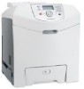
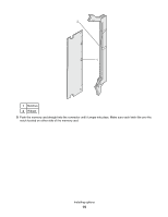
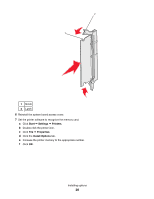
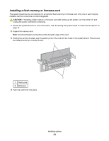
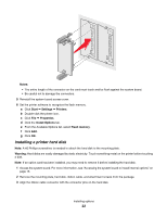
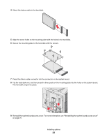
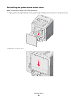
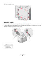
Installing an internal print server or port interface card Note: A #2 Phillips screwdriver is needed to install an internal print server or port interface card. Warning: System board electrical components are easily damaged by static electricity. Touch something metal on the printer before touching any system board electronic components or connectors. An internal print server allows connection from the printer to the local area network (LAN). An optional port interface card expands the ways the printer can connect to a computer or external print server. 1 Access the system board. For more information, see "Accessing the system board to install internal options" on page 15. 2 Unpack the internal print server or port interface card. 3 Locate the two screws on the printer that attach the metal plate to the connector slot. Remove and save the two screws. 4 Remove the metal plate covering the connector slot and save the metal plate. 5 Align the connector on the internal print server or port interface card with the connector on the system board. The cable connectors on the side of the optional card must fit through the opening in the faceplate. Push the internal print server or port interface card firmly into the card connector on the system board. 1 3 2 4 6 Insert the two screws saved from the metal plate (or the extra screws shipped with the optional card) into the holes on either side of the connector slot. Gently tighten the screws to secure the card to the system board. 7 Reinstall the system board access cover. For more information, see "Reinstalling the system board access cover" on page 25. Installing options 24
-
 1
1 -
2
-
3
-
4
-
5
-
6
-
7
-
8
-
9
-
10
-
11
-
12
-
13
-
14
-
15
-
16
-
17
-
18
-
 19
19 -
 20
20 -
 21
21 -
 22
22 -
 23
23 -
 24
24 -
 25
25 -
 26
26 -
 27
27 -
 28
28 -
 29
29 -
30
-
31
-
32
-
33
-
34
-
35
-
36
-
37
-
38
-
39
-
40
-
41
-
42
-
43
-
44
-
45
-
46
-
47
-
48
-
49
-
50
-
51
-
52
-
53
-
54
-
55
-
56
-
57
-
58
-
59
-
60
-
61
-
62
-
63
-
64
-
65
-
66
-
67
-
68
-
69
-
70
-
71
-
72
-
73
-
74
-
75
-
76
-
77
-
78
-
79
-
80
-
81
-
82
-
83
-
84
-
85
-
86
-
87
-
88
-
89
-
90
-
91
-
92
-
93
-
94
-
95
-
96
-
97
-
98
-
99
-
100
-
101
-
102
-
103
-
104
-
105
-
106
-
107
-
108
-
109
-
110
 |
 |