Lexmark E360d Service Manual - Page 169
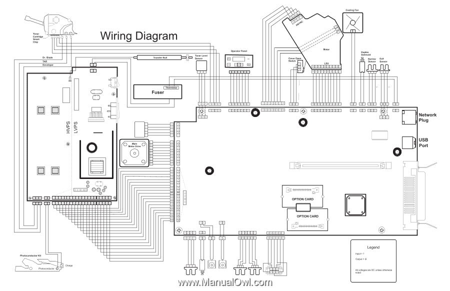
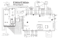
Wiring diagram
 |
View all Lexmark E360d manuals
Add to My Manuals
Save this manual to your list of manuals |
Page 169 highlights
E360d/E360dn 70S 5V Gnd TAT201 CN102 CN203 CN202 1 19 2 20 CN201 3.3V 5V 3.3V Gnd 3.3V 3.3V Gnd 3.3V 3.3V 1.7V Gnd Gnd 0.6V Gnd Gnd Gnd Gnd 5V 5V (0V) 5V Toner Patch Sensor 0V (5V) Gnd 0V (1V) (5V) 21V (24V) 21V (24V) 5V (5V) (>0V) 5V 5V (5V) 5V (5V) (>0V) 5V 5V 5V 5V 5V 24V 5V 5V 5V 5V 5V 24V 24V J501 J4 J13 J17 21 J502 With printer off, unplug this cable and turn printer back on. Check values on the cable pins. 20 19 J24 J26 J23 J25 J5 J27 J100 J7 J8 With printer off, unplug this cable and turn printer back on. Check values on the cable pins. J9 J10 J11 J12 J14 J28 3.3V 24V 3.3V Gnd 5V (1.1V) 5V Gnd 5V (1.1V) 5V Gnd 0V (24V) 24V 0V (24V) 24V 0V (24V) 24V 5V (1.1V) 5V Gnd 70S MPF Sensor Manual MPF Clutch Clutch Solenoid Paper Feed Clutch Paper In Sensor Duplex Sensor Tray 2 Connector Plugged voltage (if different) = ( ) Closed 5V 5V Gnd Open (0V) 5V 2.5V 5V 5V 5V 5V 0V (24V) 24V 24V 0V (24V) ( 0V) 5V 5V Gnd ( 0V) 5V 5V Gnd
-
 1
1 -
2
-
3
-
4
-
5
-
6
-
7
-
8
-
9
-
10
-
11
-
12
-
13
-
14
-
15
-
16
-
17
-
18
-
19
-
20
-
21
-
22
-
23
-
24
-
25
-
26
-
27
-
28
-
29
-
30
-
31
-
32
-
33
-
34
-
35
-
36
-
37
-
38
-
39
-
40
-
41
-
42
-
43
-
44
-
45
-
46
-
47
-
48
-
49
-
50
-
51
-
52
-
53
-
54
-
55
-
56
-
57
-
58
-
59
-
60
-
61
-
62
-
63
-
64
-
65
-
66
-
67
-
68
-
69
-
70
-
71
-
72
-
73
-
74
-
75
-
76
-
77
-
78
-
79
-
80
-
81
-
82
-
83
-
84
-
85
-
86
-
87
-
88
-
89
-
90
-
91
-
92
-
93
-
94
-
95
-
96
-
97
-
98
-
99
-
100
-
101
-
102
-
103
-
104
-
105
-
106
-
107
-
108
-
109
-
110
-
111
-
112
-
113
-
114
-
115
-
116
-
117
-
118
-
119
-
120
-
121
-
122
-
123
-
124
-
125
-
126
-
127
-
128
-
129
-
130
-
131
-
132
-
133
-
134
-
135
-
136
-
137
-
138
-
139
-
140
-
141
-
142
-
143
-
144
-
145
-
146
-
147
-
148
-
149
-
150
-
151
-
152
-
153
-
154
-
155
-
156
-
157
-
158
-
159
-
160
-
161
-
162
-
163
-
 164
164 -
 165
165 -
 166
166 -
 167
167 -
 168
168 -
 169
169 -
 170
170
 |
 |