Lexmark E360d Service Manual - Page 48
Service checks, Controller board service check - service manual
 |
View all Lexmark E360d manuals
Add to My Manuals
Save this manual to your list of manuals |
Page 48 highlights
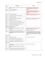
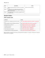
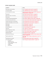
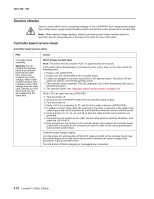
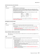
4513-420, -430 Service checks Service checks which involve measuring voltages on the LVPS/HVPS (low voltage power supply/ high voltage power supply board) should be performed with the printer positioned on its back side. Note: When making voltage readings, always use frame ground unless another ground is specified. See the wiring diagram in the back of the book for more information. Controller board service check Controller board service check FRU Controller board assembly Warning: Do not replace the operator panel and controller board at the same time. Each card contains the printer settings. When either of these cards is new, it obtains some of the settings from the other card. Settings are lost when both are new and replaced at the same time. Action POST (Power-On Self Test) Note: The printer should complete POST in approximately 30 seconds. If the printer fails to display lights or activate the drive motor, fuser, or fan, then check the following order: 1. Power to the LVPS/HVPS 2. Power from the LVPS/HVPS to the controller board 3. Cables are plugged in correctly, especially for the operator panel. The printer will not power-up without a functioning operator panel. 4. The controller board assembly. The LED adjacent to J12 will be illuminated if the card is powered and good. 5. The operator panel. See "Operator panel service check" on page 2-27. Verify +24 V dc input from the LVPS/HVPS. 1. Turn the printer off. 2. Disconnect the LVPS/HVPS cable from the controller board at J502. 3. Turn the printer on. 4. Verify +24 V dc on positions 6, 17, and 19 of the cable connector (LVPS/HVPS). 5. If voltage is correct, then check the continuity in the other conductors of the cable. If the cable is good, then turn the printer off, and check the connectors to the controller board. 6. Verify that pins 10, 12, 14, 16, and 18 on both the cable and the card connector are grounded. 7. If grounds are not correct on the cable, but the cable passes continuity otherwise, then check the LVPS/HVPS. 8. If the grounds are not correct on the controller board, then replace the controller board. (Check with one probe on the connector pin and the other on the card's ground plane found at each screw head.) Controller board voltage outputs Turn the printer off, and plug the LVPS/HVPS cable into J502 of the controller board. See the wiring diagram at the end of the manual which identifies the output voltages and grounds for a good controller board. Turn the printer off before plugging or unplugging any connectors. 2-22 Lexmark™ E360d, E360dn
-
 1
1 -
2
-
3
-
4
-
5
-
6
-
7
-
8
-
9
-
10
-
11
-
12
-
13
-
14
-
15
-
16
-
17
-
18
-
19
-
20
-
21
-
22
-
23
-
24
-
25
-
26
-
27
-
28
-
29
-
30
-
31
-
32
-
33
-
34
-
35
-
36
-
37
-
38
-
39
-
40
-
41
-
42
-
 43
43 -
 44
44 -
 45
45 -
 46
46 -
 47
47 -
 48
48 -
 49
49 -
 50
50 -
 51
51 -
 52
52 -
 53
53 -
54
-
55
-
56
-
57
-
58
-
59
-
60
-
61
-
62
-
63
-
64
-
65
-
66
-
67
-
68
-
69
-
70
-
71
-
72
-
73
-
74
-
75
-
76
-
77
-
78
-
79
-
80
-
81
-
82
-
83
-
84
-
85
-
86
-
87
-
88
-
89
-
90
-
91
-
92
-
93
-
94
-
95
-
96
-
97
-
98
-
99
-
100
-
101
-
102
-
103
-
104
-
105
-
106
-
107
-
108
-
109
-
110
-
111
-
112
-
113
-
114
-
115
-
116
-
117
-
118
-
119
-
120
-
121
-
122
-
123
-
124
-
125
-
126
-
127
-
128
-
129
-
130
-
131
-
132
-
133
-
134
-
135
-
136
-
137
-
138
-
139
-
140
-
141
-
142
-
143
-
144
-
145
-
146
-
147
-
148
-
149
-
150
-
151
-
152
-
153
-
154
-
155
-
156
-
157
-
158
-
159
-
160
-
161
-
162
-
163
-
164
-
165
-
166
-
167
-
168
-
169
-
170
 |
 |