Lexmark E360d Service Manual - Page 81
Printhead assembly mechanical adjustment
 |
View all Lexmark E360d manuals
Add to My Manuals
Save this manual to your list of manuals |
Page 81 highlights
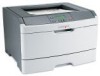
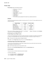
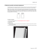
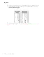
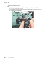
4513-420, -430 Printhead assembly mechanical adjustment A printhead needs to be correctly positioned after it has been removed. Use a pencil to mark the screw locations of the old printhead on the metal frame. Align the new printhead relative to the location of the old printhead. Note: Skew is caused by a sheet being fed through the printer while misaligned. The entire image is rotated relative to the sheet edges. However, a mechanically misaligned printhead causes the horizontal lines to appear skewed while the vertical lines remain parallel to the vertical edges.There are no adjustments for skew. Check the pick roll (paper pick assembly) for wear, the paper path for obstructions, the fuser for proper setting, and the tray paper guides for fit to the media. Paper feed skew Printhead misalignment To adjust the printhead: 1. Enter the Diagnostics Menu. See "Entering Diagnostics menu" on page 3-5. 2. Select PRINT TESTS. 3. Select Tray 1. 4. Select Single. 5. Fold the printed test page on the left side so that a few millimeters of grid lines wrap around the outside of the fold. See photo below. 6. Fold a second vertical fold near the center so that the left side top edge aligns with the right side top edge. Diagnostic aids 3-17
-
 1
1 -
2
-
3
-
4
-
5
-
6
-
7
-
8
-
9
-
10
-
11
-
12
-
13
-
14
-
15
-
16
-
17
-
18
-
19
-
20
-
21
-
22
-
23
-
24
-
25
-
26
-
27
-
28
-
29
-
30
-
31
-
32
-
33
-
34
-
35
-
36
-
37
-
38
-
39
-
40
-
41
-
42
-
43
-
44
-
45
-
46
-
47
-
48
-
49
-
50
-
51
-
52
-
53
-
54
-
55
-
56
-
57
-
58
-
59
-
60
-
61
-
62
-
63
-
64
-
65
-
66
-
67
-
68
-
69
-
70
-
71
-
72
-
73
-
74
-
75
-
 76
76 -
 77
77 -
 78
78 -
 79
79 -
 80
80 -
 81
81 -
 82
82 -
 83
83 -
 84
84 -
 85
85 -
 86
86 -
87
-
88
-
89
-
90
-
91
-
92
-
93
-
94
-
95
-
96
-
97
-
98
-
99
-
100
-
101
-
102
-
103
-
104
-
105
-
106
-
107
-
108
-
109
-
110
-
111
-
112
-
113
-
114
-
115
-
116
-
117
-
118
-
119
-
120
-
121
-
122
-
123
-
124
-
125
-
126
-
127
-
128
-
129
-
130
-
131
-
132
-
133
-
134
-
135
-
136
-
137
-
138
-
139
-
140
-
141
-
142
-
143
-
144
-
145
-
146
-
147
-
148
-
149
-
150
-
151
-
152
-
153
-
154
-
155
-
156
-
157
-
158
-
159
-
160
-
161
-
162
-
163
-
164
-
165
-
166
-
167
-
168
-
169
-
170
 |
 |