Lexmark E360d Service Manual - Page 82
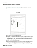
Printhead assembly electronic adjustment on, The printhead
 |
View all Lexmark E360d manuals
Add to My Manuals
Save this manual to your list of manuals |
Page 82 highlights
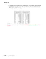
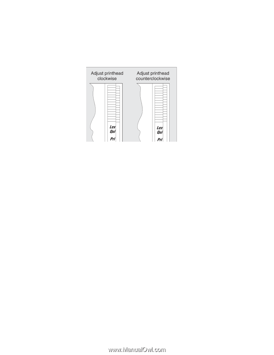
4513-420, -430 7. If the grid lines of the right flap align below the corresponding lines on the left flap, then adjust the printhead clockwise relative to the printer and recheck. (See the left side of the figure below.) If the grid lines of the left flap align below the corresponding lines of the right side, then adjust the printhead counterclockwise. (See the right side of the figure below.) 8. After obtaining a properly adjusted image on the paper, tighten all three screws. Note: The printhead must be aligned electronically. See "Printhead assembly electronic adjustment" on page 3-16. 3-18 Lexmark™ E360d, E360dn
-
 1
1 -
2
-
3
-
4
-
5
-
6
-
7
-
8
-
9
-
10
-
11
-
12
-
13
-
14
-
15
-
16
-
17
-
18
-
19
-
20
-
21
-
22
-
23
-
24
-
25
-
26
-
27
-
28
-
29
-
30
-
31
-
32
-
33
-
34
-
35
-
36
-
37
-
38
-
39
-
40
-
41
-
42
-
43
-
44
-
45
-
46
-
47
-
48
-
49
-
50
-
51
-
52
-
53
-
54
-
55
-
56
-
57
-
58
-
59
-
60
-
61
-
62
-
63
-
64
-
65
-
66
-
67
-
68
-
69
-
70
-
71
-
72
-
73
-
74
-
75
-
76
-
 77
77 -
 78
78 -
 79
79 -
 80
80 -
 81
81 -
 82
82 -
 83
83 -
 84
84 -
 85
85 -
 86
86 -
 87
87 -
88
-
89
-
90
-
91
-
92
-
93
-
94
-
95
-
96
-
97
-
98
-
99
-
100
-
101
-
102
-
103
-
104
-
105
-
106
-
107
-
108
-
109
-
110
-
111
-
112
-
113
-
114
-
115
-
116
-
117
-
118
-
119
-
120
-
121
-
122
-
123
-
124
-
125
-
126
-
127
-
128
-
129
-
130
-
131
-
132
-
133
-
134
-
135
-
136
-
137
-
138
-
139
-
140
-
141
-
142
-
143
-
144
-
145
-
146
-
147
-
148
-
149
-
150
-
151
-
152
-
153
-
154
-
155
-
156
-
157
-
158
-
159
-
160
-
161
-
162
-
163
-
164
-
165
-
166
-
167
-
168
-
169
-
170
 |
 |
3-18
Lexmark™ E360d, E360dn
4513-420, -430
7.
If the grid lines of the right flap align below the corresponding lines on the left flap, then adjust the printhead
clockwise relative to the printer and recheck. (See the left side of the figure below.) If the grid lines of the
left flap align below the corresponding lines of the right side, then adjust the printhead counterclockwise.
(See the right side of the figure below.)
8.
After obtaining a properly adjusted image on the paper, tighten all three screws.
Note:
The printhead
must
be aligned electronically. See
“Printhead assembly electronic adjustment” on
page 3-16
.