Lexmark E360d Service Manual - Page 89
When installing the controller board, place the USB port and parallel port screws first
 |
View all Lexmark E360d manuals
Add to My Manuals
Save this manual to your list of manuals |
Page 89 highlights
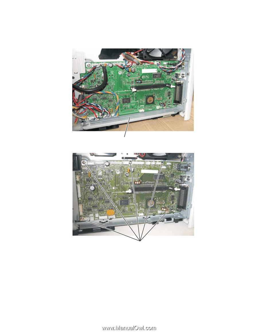
4513-420, -430 3. Disconnect all of the cables from the controller board. Note: A drip guard (B) has been added below the controller board. The drip guard may need to be removed to access to the controller board. B 4. Remove the five screws (C) from the controller board. C 5. Lift the controller board, and remove. Note: When installing the controller board, place the USB port and parallel port screws first, and then place the controller board screws. Repair information 4-7
-
 1
1 -
2
-
3
-
4
-
5
-
6
-
7
-
8
-
9
-
10
-
11
-
12
-
13
-
14
-
15
-
16
-
17
-
18
-
19
-
20
-
21
-
22
-
23
-
24
-
25
-
26
-
27
-
28
-
29
-
30
-
31
-
32
-
33
-
34
-
35
-
36
-
37
-
38
-
39
-
40
-
41
-
42
-
43
-
44
-
45
-
46
-
47
-
48
-
49
-
50
-
51
-
52
-
53
-
54
-
55
-
56
-
57
-
58
-
59
-
60
-
61
-
62
-
63
-
64
-
65
-
66
-
67
-
68
-
69
-
70
-
71
-
72
-
73
-
74
-
75
-
76
-
77
-
78
-
79
-
80
-
81
-
82
-
83
-
 84
84 -
 85
85 -
 86
86 -
 87
87 -
 88
88 -
 89
89 -
 90
90 -
 91
91 -
 92
92 -
 93
93 -
 94
94 -
95
-
96
-
97
-
98
-
99
-
100
-
101
-
102
-
103
-
104
-
105
-
106
-
107
-
108
-
109
-
110
-
111
-
112
-
113
-
114
-
115
-
116
-
117
-
118
-
119
-
120
-
121
-
122
-
123
-
124
-
125
-
126
-
127
-
128
-
129
-
130
-
131
-
132
-
133
-
134
-
135
-
136
-
137
-
138
-
139
-
140
-
141
-
142
-
143
-
144
-
145
-
146
-
147
-
148
-
149
-
150
-
151
-
152
-
153
-
154
-
155
-
156
-
157
-
158
-
159
-
160
-
161
-
162
-
163
-
164
-
165
-
166
-
167
-
168
-
169
-
170
 |
 |
Repair information
4-7
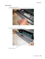
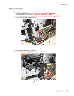
4513-420, -430
3.
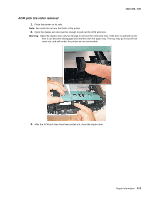
Disconnect all of the cables from the controller board.
Note:
A drip guard (B) has been added below the controller board. The drip guard may need to be removed to
access to the controller board.
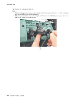
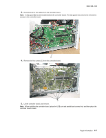
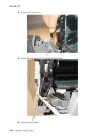
4.
Remove the five screws (C) from the controller board.
5.
Lift the controller board, and remove.
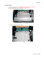
Note:
When installing the controller board, place the USB port and parallel port screws first, and then place the
controller board screws.
B
C