Lexmark X342N Service Manual - Page 136
Controller card pin assignments, J3 ADF
 |
UPC - 734646256292
View all Lexmark X342N manuals
Add to My Manuals
Save this manual to your list of manuals |
Page 136 highlights
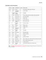
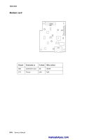
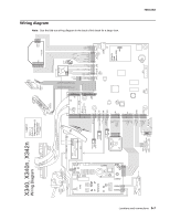
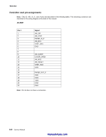
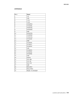
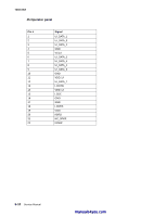
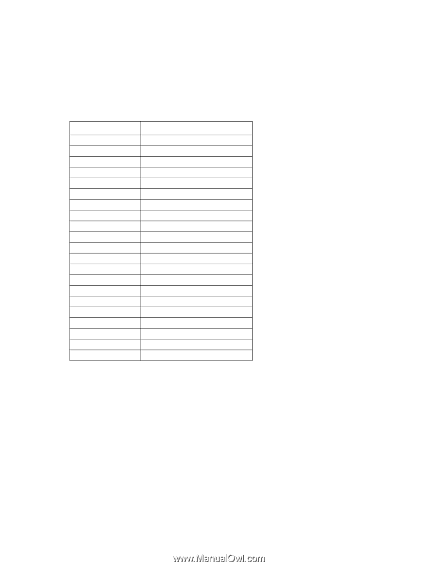
7003-XXX Controller card pin assignments Note: Only J3, J69, J5, J1, and J4 pins are described in the following tables. The remaining connectors are described in the wiring diagram at the back of the manual. J3 ADF Pin # 1 2 3 4 5 6 7 8 9 10 11 12 13 14 15 16 17 18 19 20 22 Signal AM_DIR AM_STEP PAPER_IN_P AM_MS1 VREF_SW1 GND AM_SLEEP COVER_OPEN AM_MS2 AM_RESET VREF_SW2 GND PAPER_OUT_P GND GND +24V GND GND Note: Pin 21 does not have a connection. 5-8 Service Manual manuals4you.com
-
 1
1 -
2
-
3
-
4
-
5
-
6
-
7
-
8
-
9
-
10
-
11
-
12
-
13
-
14
-
15
-
16
-
17
-
18
-
19
-
20
-
21
-
22
-
23
-
24
-
25
-
26
-
27
-
28
-
29
-
30
-
31
-
32
-
33
-
34
-
35
-
36
-
37
-
38
-
39
-
40
-
41
-
42
-
43
-
44
-
45
-
46
-
47
-
48
-
49
-
50
-
51
-
52
-
53
-
54
-
55
-
56
-
57
-
58
-
59
-
60
-
61
-
62
-
63
-
64
-
65
-
66
-
67
-
68
-
69
-
70
-
71
-
72
-
73
-
74
-
75
-
76
-
77
-
78
-
79
-
80
-
81
-
82
-
83
-
84
-
85
-
86
-
87
-
88
-
89
-
90
-
91
-
92
-
93
-
94
-
95
-
96
-
97
-
98
-
99
-
100
-
101
-
102
-
103
-
104
-
105
-
106
-
107
-
108
-
109
-
110
-
111
-
112
-
113
-
114
-
115
-
116
-
117
-
118
-
119
-
120
-
121
-
122
-
123
-
124
-
125
-
126
-
127
-
128
-
129
-
130
-
 131
131 -
 132
132 -
 133
133 -
 134
134 -
 135
135 -
 136
136 -
 137
137 -
 138
138 -
 139
139 -
 140
140 -
 141
141 -
142
-
143
-
144
-
145
-
146
-
147
-
148
-
149
-
150
-
151
-
152
-
153
-
154
-
155
-
156
-
157
-
158
-
159
-
160
-
161
-
162
-
163
 |
 |
5-8
Service Manual
7003-XXX
Controller card pin assignments
Note:
Only J3, J69, J5, J1, and J4 pins are described in the following tables. The remaining connectors are
described in the wiring diagram at the back of the manual.
J3 ADF
Note:
Pin 21 does not have a connection.
Pin #
Signal
1
AM_DIR
2
AM_STEP
3
PAPER_IN_P
4
AM_MS1
5
VREF_SW1
6
GND
7
8
9
AM_SLEEP
10
COVER_OPEN
11
AM_MS2
12
AM_RESET
13
VREF_SW2
14
GND
15
16
PAPER_OUT_P
17
GND
18
GND
19
+24V
20
GND
22
GND
manuals4you.com
manuals4you.com