Lexmark X342N Service Manual - Page 156
X340/X342n, Menu button
 |
UPC - 734646256292
View all Lexmark X342N manuals
Add to My Manuals
Save this manual to your list of manuals |
Page 156 highlights
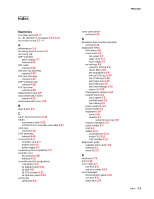
7003-XXX service error codes 2-7 sub errors 2-14 user attendance messages 2-10 ESD-sensitive parts 4-1 exit sensor removal 4-17 extender cover removal 4-2 F fan removal 4-18 Fax specifications 1-6 Flatbed cover removal 4-48 fonts 1-2 frame, parts catalog 7-10 front access cover removal 4-2 fuser removal 4-20 service check 2-23 fuser idle gear links removal 4-21 fuser power cable removal 4-22 G general information 1-1 H handling ESD-sensitive parts 4-1 I Input roller clutch and lever removal 4-23 Input sensor #1 removal 4-24 input sensor #2(manual feed) removal 4-25 J Job setup buttons 2-4 L left side cover removal 4-3 locations 5-1 ADF 5-2 controller card 5-4 controller card connections 5-5 controller card pin assignments 5-8 front view 5-1 modem card 5-6 power supply board 5-3 power supply board connections 5-3 rear view 5-1 wiring diagram 5-7 Lower right side cover removal 4-10 LVPS/HVPS card assembly I-2 Service Manual removal 4-26 LVPS?HVPS to controller card cable removal 4-27 M maintenance approach 1-1 manual feed clutch assembly 4-28 input sensor #2 4-25 print media types and sizes 1-4 manual feed clutch removal 4-28 Media trays and supply capacity 1-3 memory 1-1 Menu button 2-5 menus printing 3-1 X340/X342n diagnostics menu 3-2 messages paper jam messages 2-9 service error codes 2-7 user attendance messages 2-10 MFP specifications 1-1 connectivity and compatibility 1-2 fonts 1-2 memory 1-1 minimum clearance requirements 1-1 print speed 1-1 trays and supply capacities 1-3 types of print media 1-4 mfp symptoms 2-2 minimum clearance requirements 1-1 Mode selection 2-4 modem card removal 4-54 modem speaker assembly removal 4-55 Multi-purpose job setup buttons 2-5 N Navigation keys 2-5 O operator panel buttons 2-4 service check 2-27 operator panel assembly removal 4-30 P paper exit guide assembly removal 4-31 paper jams 2-9 tips on preventing 1-6 parts catalog covers 7-2 covers 7-3 electronics 7-8 electronics 7-9 manuals4you.com
-
 1
1 -
2
-
3
-
4
-
5
-
6
-
7
-
8
-
9
-
10
-
11
-
12
-
13
-
14
-
15
-
16
-
17
-
18
-
19
-
20
-
21
-
22
-
23
-
24
-
25
-
26
-
27
-
28
-
29
-
30
-
31
-
32
-
33
-
34
-
35
-
36
-
37
-
38
-
39
-
40
-
41
-
42
-
43
-
44
-
45
-
46
-
47
-
48
-
49
-
50
-
51
-
52
-
53
-
54
-
55
-
56
-
57
-
58
-
59
-
60
-
61
-
62
-
63
-
64
-
65
-
66
-
67
-
68
-
69
-
70
-
71
-
72
-
73
-
74
-
75
-
76
-
77
-
78
-
79
-
80
-
81
-
82
-
83
-
84
-
85
-
86
-
87
-
88
-
89
-
90
-
91
-
92
-
93
-
94
-
95
-
96
-
97
-
98
-
99
-
100
-
101
-
102
-
103
-
104
-
105
-
106
-
107
-
108
-
109
-
110
-
111
-
112
-
113
-
114
-
115
-
116
-
117
-
118
-
119
-
120
-
121
-
122
-
123
-
124
-
125
-
126
-
127
-
128
-
129
-
130
-
131
-
132
-
133
-
134
-
135
-
136
-
137
-
138
-
139
-
140
-
141
-
142
-
143
-
144
-
145
-
146
-
147
-
148
-
149
-
150
-
 151
151 -
 152
152 -
 153
153 -
 154
154 -
 155
155 -
 156
156 -
 157
157 -
 158
158 -
 159
159 -
 160
160 -
 161
161 -
162
-
163
 |
 |