Lexmark X342N Service Manual - Page 44
Cover interlock switch service check, Dead machine service check
 |
UPC - 734646256292
View all Lexmark X342N manuals
Add to My Manuals
Save this manual to your list of manuals |
Page 44 highlights
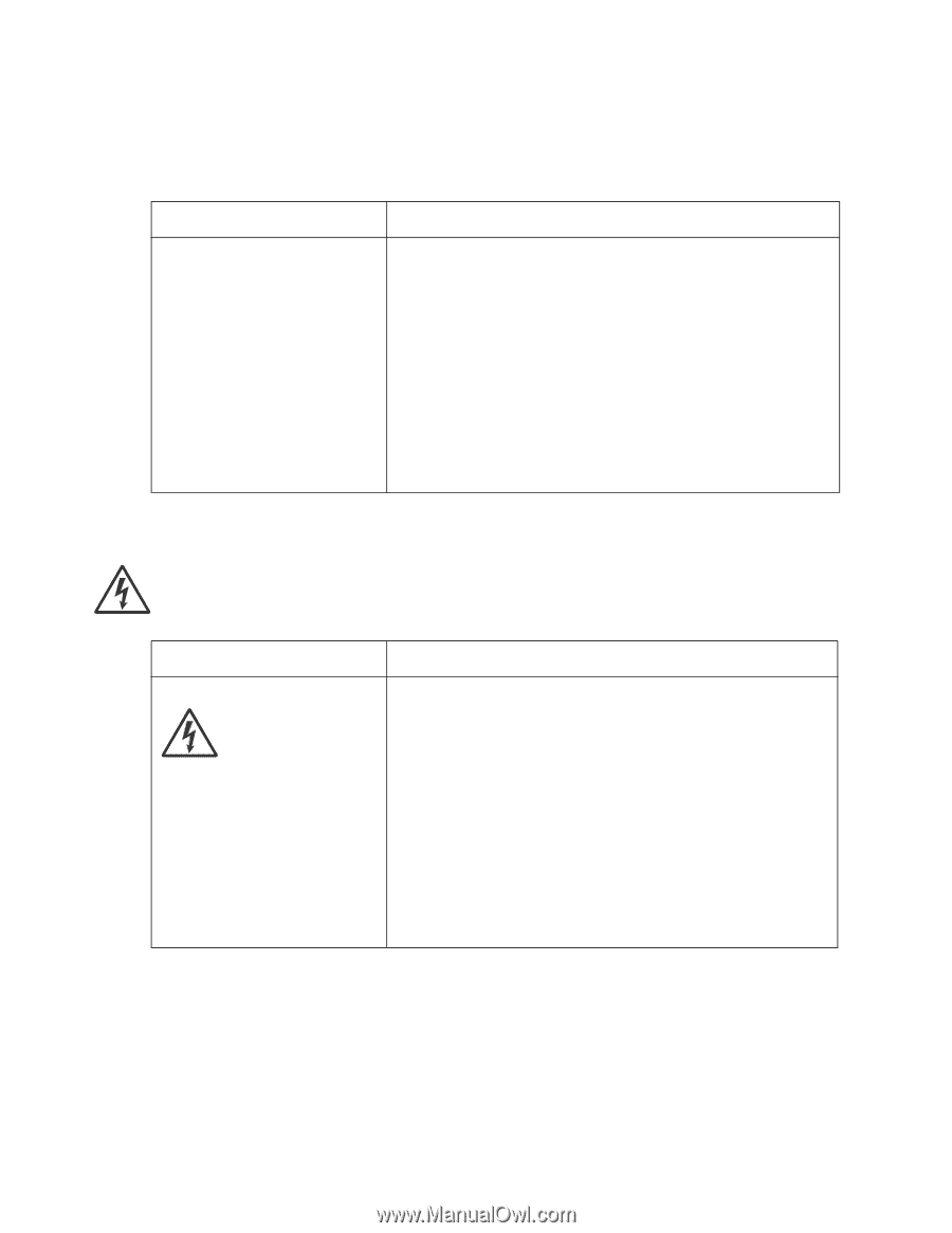
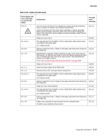
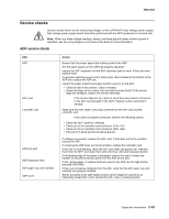
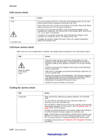
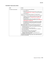
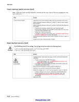
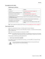
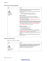
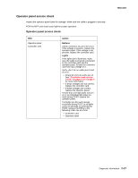
7003-XXX Cover interlock switch service check Note: Make sure a print cartridge assembly is installed and the cover closes all the way, engaging the cover open switch lever. FRU Cover interlock switch Action Disconnect the cover interlock cable from the controller card at J13. Verify continuity between cable pin 1 and pin 2 with the door closed but not open. Verify continuity between cable pin 1 and pin 3 with the door open but not closed. • If either fail continuity, replace the cover interlock switch. • If both pass continuity, turn the MFP on and verify +5 V dc on pin 2 at J13 on the controller card. • Verify pins 1 and 3 are ground. • If voltage or ground is not present, see "Controller card service check" on page 2-21 for more information. Verify discontinuity between pins 2 and 3 whether the door is open or closed. Replace the cover interlock switch if faulty. Dead machine service check CAUTIONCheck the AC line voltage. The voltage should be within the following limits: • 100 V ac (volts alternating current) - 127 V ac for the 110 V MFP • 200 V ac - 240 V ac for the 220 V MFP FRU LVPS/HVPS Action Unplug the MFP, and check the fuses on the LVPS/HVPS board for continuity. • If open, replace the LVPS/HVPS board. - If fuse opens again, see "LVPS/HVPS service check" on page 2-25 for more information. • If not open, unplug the cables at CN102 and CN201 (fuser and controller card respectively). Plug LVPS/HVPS board to source, and turn switch on. Verify 24 V dc on pins 9 and 10 at connector CN201. Verify line voltage (110 or 220 V ac) across pins 1 and 2 of CN102. • If either voltage is not correct, replace the LVPS/HVPS board. • If both voltages are correct, check the controller card. See "Controller card service check" on page 2-21 for more information. Verify grounds. 2-22 Service Manual manuals4you.com
-
 1
1 -
2
-
3
-
4
-
5
-
6
-
7
-
8
-
9
-
10
-
11
-
12
-
13
-
14
-
15
-
16
-
17
-
18
-
19
-
20
-
21
-
22
-
23
-
24
-
25
-
26
-
27
-
28
-
29
-
30
-
31
-
32
-
33
-
34
-
35
-
36
-
37
-
38
-
 39
39 -
 40
40 -
 41
41 -
 42
42 -
 43
43 -
 44
44 -
 45
45 -
 46
46 -
 47
47 -
 48
48 -
 49
49 -
50
-
51
-
52
-
53
-
54
-
55
-
56
-
57
-
58
-
59
-
60
-
61
-
62
-
63
-
64
-
65
-
66
-
67
-
68
-
69
-
70
-
71
-
72
-
73
-
74
-
75
-
76
-
77
-
78
-
79
-
80
-
81
-
82
-
83
-
84
-
85
-
86
-
87
-
88
-
89
-
90
-
91
-
92
-
93
-
94
-
95
-
96
-
97
-
98
-
99
-
100
-
101
-
102
-
103
-
104
-
105
-
106
-
107
-
108
-
109
-
110
-
111
-
112
-
113
-
114
-
115
-
116
-
117
-
118
-
119
-
120
-
121
-
122
-
123
-
124
-
125
-
126
-
127
-
128
-
129
-
130
-
131
-
132
-
133
-
134
-
135
-
136
-
137
-
138
-
139
-
140
-
141
-
142
-
143
-
144
-
145
-
146
-
147
-
148
-
149
-
150
-
151
-
152
-
153
-
154
-
155
-
156
-
157
-
158
-
159
-
160
-
161
-
162
-
163
 |
 |