Lexmark X342N Service Manual - Page 98
LVPS/HVPS card assembly removal, Power supply ID on Rear cover removal on,
 |
UPC - 734646256292
View all Lexmark X342N manuals
Add to My Manuals
Save this manual to your list of manuals |
Page 98 highlights
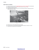
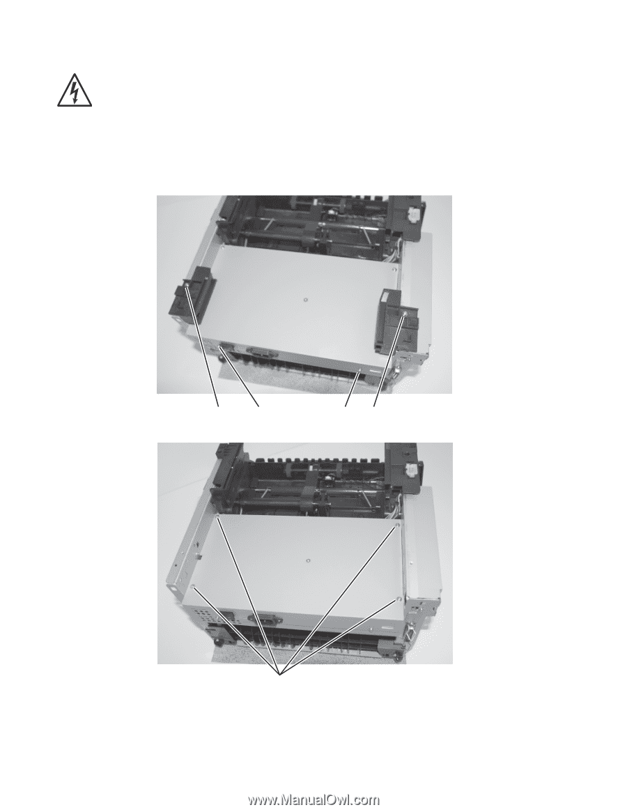
7003-XXX LVPS/HVPS card assembly removal Note: After installing the new power supply, ensure that the correct firmware setting for the power supply is set. See "Power supply ID" on page 3-4. 1. Remove the cover extender (if installed), paper tray, and the rear cover. See "Rear cover removal" on page 4-5 for more information. 2. Remove two screws (A), one left of the power switch and the other at the opposite side of the panel. 3. Place the MFP onto its back with the rear and bottom of the MFP in view. 4. Remove the screws (B) securing the two foot brackets. B A AB 5. Remove four screws (C) in the bottom of the metal cover. 4-26 Service Manual C manuals4you.com
-
 1
1 -
2
-
3
-
4
-
5
-
6
-
7
-
8
-
9
-
10
-
11
-
12
-
13
-
14
-
15
-
16
-
17
-
18
-
19
-
20
-
21
-
22
-
23
-
24
-
25
-
26
-
27
-
28
-
29
-
30
-
31
-
32
-
33
-
34
-
35
-
36
-
37
-
38
-
39
-
40
-
41
-
42
-
43
-
44
-
45
-
46
-
47
-
48
-
49
-
50
-
51
-
52
-
53
-
54
-
55
-
56
-
57
-
58
-
59
-
60
-
61
-
62
-
63
-
64
-
65
-
66
-
67
-
68
-
69
-
70
-
71
-
72
-
73
-
74
-
75
-
76
-
77
-
78
-
79
-
80
-
81
-
82
-
83
-
84
-
85
-
86
-
87
-
88
-
89
-
90
-
91
-
92
-
 93
93 -
 94
94 -
 95
95 -
 96
96 -
 97
97 -
 98
98 -
 99
99 -
 100
100 -
 101
101 -
 102
102 -
 103
103 -
104
-
105
-
106
-
107
-
108
-
109
-
110
-
111
-
112
-
113
-
114
-
115
-
116
-
117
-
118
-
119
-
120
-
121
-
122
-
123
-
124
-
125
-
126
-
127
-
128
-
129
-
130
-
131
-
132
-
133
-
134
-
135
-
136
-
137
-
138
-
139
-
140
-
141
-
142
-
143
-
144
-
145
-
146
-
147
-
148
-
149
-
150
-
151
-
152
-
153
-
154
-
155
-
156
-
157
-
158
-
159
-
160
-
161
-
162
-
163
 |
 |
4-26
Service Manual
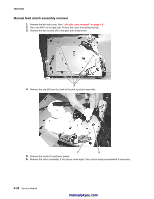
7003-XXX
LVPS/HVPS card assembly removal
Note:
After installing the new power supply, ensure that the correct firmware setting for the power supply is
set. See
“Power supply ID” on page 3-4
.
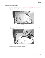
1.
Remove the cover extender (if installed), paper tray, and the rear cover. See
“Rear cover removal” on
page 4-5
for more information.
2.
Remove two screws (A), one left of the power switch and the other at the opposite side of the panel.
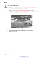
3.
Place the MFP onto its back with the rear and bottom of the MFP in view.
4.
Remove the screws (B) securing the two foot brackets.
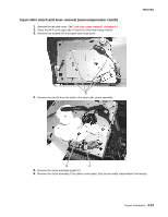
5.
Remove four screws (C) in the bottom of the metal cover
.
A
B
A
B
C
manuals4you.com
manuals4you.com