Lexmark X644E Service Manual
Lexmark X644E - With Modem Taa/gov Manual
 |
UPC - 734646093156
View all Lexmark X644E manuals
Add to My Manuals
Save this manual to your list of manuals |
Lexmark X644E manual content summary:
- Lexmark X644E | Service Manual - Page 1
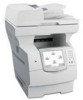
Edition: February 27, 2007 Lexmark™ X642e, X644e, X646e MFP 7002-xxx • Table of Contents • Start Diagnostics • Safety and Notices • Trademarks • Index Lexmark and Lexmark with diamond design are trademarks of Lexmark International, Inc., registered in the United States and/or other countries. - Lexmark X644E | Service Manual - Page 2
include technical inaccuracies or typographical errors. Changes are periodically made to Lexmark International, Inc. LEXFAX is a service mark of Lexmark International, Inc. Other trademarks are the property of their respective owners. © 2007 Lexmark International, Inc. All rights reserved. UNITED - Lexmark X644E | Service Manual - Page 3
2-1 User status and attendance messages 2-1 Additional information 2-1 Understanding the MFP operator panel 2-2 MFP operator panels 2-2 Home screen and Home screen buttons 2-4 Buttons and touchscreen icon buttons 2-4 Menus 2-9 Symptom tables 2-10 Printer symptoms 2-10 Scanner-ADF symptoms - Lexmark X644E | Service Manual - Page 4
User attendance messages-paper jams and paper handling errors (2xx.xx 2-57 Service checks 2-95 202.03 Error code service check 2-95 202.06 Error code service check 2-95 290.00 Error code service check 2-96 290.01 Error code service check 2-98 290.02 Error code service check 2-100 290.10 Error - Lexmark X644E | Service Manual - Page 5
Menu button service check-model X642e 2-154 Operator panel right cover assembly service check 2-154 Options service check 2-155 Flash memory option(s 2-155 DRAM memory option(s 2-155 Hard disk option 2-155 Output bin sensor standard tray service check 2-156 Paper feed service check-printer - Lexmark X644E | Service Manual - Page 6
Scanner Manual Registration 3-23 Sensor Tests 3-23 Configuration menu (CONFIG MENU 3-24 Entering Configuration Menu 3-24 Available menus 3-24 Maintenance Page Count 3-25 Reset Maintenance Counter 3-25 Print Quality Pages 3-26 SIZE SENSING 3-26 Panel Menus 3-27 PPDS Emulation 3-27 Factory - Lexmark X644E | Service Manual - Page 7
Paper Jam Open Duplex Rear Door 3-48 Clearing ADF jams 3-49 290, 291, 292, and 294 Scanner Jams 3-49 Repair information 4-1 Handling ESD-sensitive parts 4-1 Adjustment procedures 4-2 Fuser solenoid adjustment 4-2 Gap adjustment 4-2 Printhead assembly adjustment-printer 4-2 Paper alignment - Lexmark X644E | Service Manual - Page 8
4-33 Flatbed paper length sensor assembly removal 4-35 Flatbed scan assembly removal 4-38 Flatbed scan motor assembly removal 4-41 Hard disk removal 4-44 Home sensor removal 4-46 Lower exit guide assembly removal 4-47 Pickup solenoid assembly removal 4-48 Scanner control card removal 4-48 - Lexmark X644E | Service Manual - Page 9
Maintenance kit 6-1 Cleaning the scanner glass, cushions, and strips 6-2 Parts catalog 7-1 How to use this parts catalog 7-1 Assembly 1: Covers-printer (model X642e 7-2 Assembly 2: Cover-printer (models X644e and X646e 7-6 Assembly 3: Covers-ADF scanner 7-8 Assembly 4: Frame 1 7-10 Assembly - Lexmark X644E | Service Manual - Page 10
Duplex option 7-63 Assembly 40: Envelope feeder 7-64 Assembly 41: High-capacity feeder 1 7-66 Assembly 42: High-capacity feeder 2 7-68 Assembly 43: High-capacity feeder 3 7-69 Assembly 44: High-capacity feeder 4 7-70 Assembly 45: Options 7-71 Index I-1 Part number index I-9 x Service Manual - Lexmark X644E | Service Manual - Page 11
in the wavelength region of 770-795 nanometers. The laser system and printer are designed so there is never any human access to laser radiation above a Class I level during normal operation, user maintenance, or prescribed service condition. Laser Der Drucker erfüllt gemäß amtlicher Bestätigung der - Lexmark X644E | Service Manual - Page 12
e 795 nanómetros. O sistema e a impressora laser foram concebidos de forma a nunca existir qualquer possiblidade de acesso humano a radiação laser superior a um nível de Classe I durante a operação normal, a manutenção feita pelo utilizador ou condições de assistência prescritas. xii Service Manual - Lexmark X644E | Service Manual - Page 13
Subchapter J, voor andere landen in IEC 60825-1. Laserprodukten van klasse I worden niet als ongevaarlijk aangemerkt. De printer is voorzien van een laser van klasse IIIb (3b), dat wil zeggen een gallium arsenide-laser van 5 milliwatt met een golflengte van 770-795 nanometer. Het lasergedeelte en de - Lexmark X644E | Service Manual - Page 14
ndning, underhåll som utförs av användaren eller annan föreskriven serviceåtgärd. Laser-melding Skriveren er godkjent i USA etter kravene i DHHS 21 CFR, Avís sobre el Làser Segons ha estat certificat als Estats Units, aquesta impressora compleix els requisits de DHHS 21 CFR, apartat Service Manual - Lexmark X644E | Service Manual - Page 15
Japanese Laser Notice 7002-xxx Laser notices xv - Lexmark X644E | Service Manual - Page 16
7002-xxx Korean Laser Notice xvi Service Manual - Lexmark X644E | Service Manual - Page 17
information • The safety of this product is based on testing and approvals of the original design and specific components. The manufacturer is not responsible for safety in the event of use of unauthorized replacement parts. • The maintenance information for this product has been prepared for - Lexmark X644E | Service Manual - Page 18
peligro y tomar las precauciones necesarias. • PRECAUCIÓN: este símbolo indica que el voltaje de la parte del equipo con la que está trabajando es peligroso. Antes de empezar, desenchufe el equipo o de estar ligado à corrente eléctrica para realizar a tarefa necessária. -xviii Service Manual - Lexmark X644E | Service Manual - Page 19
producte. El personal professional ha d'estar-ne assabentat i prendre les mesures convenients. • PRECAUCIÓ: aquest símbol indica que el voltatge de la part de l'equip amb la qual esteu treballant és perillós. Abans de començar, desendolleu l'equip o extremeu les precaucions si, per treballar - Lexmark X644E | Service Manual - Page 20
contains an error indicator table, symptom tables, and service checks used to isolate failing field replaceable units (FRUs). 3. Diagnostic aids contains tests and checks used to locate or repeat symptoms of printer problems. 4. Repair information provides instructions for making printer adjustments - Lexmark X644E | Service Manual - Page 21
approach The diagnostic information in this manual leads you to the correct field replaceable unit (FRU) or part. Use the service error codes, user status messages, user error messages, service checks, and diagnostic aids to determine the MPF problem and repair the failure. After you complete - Lexmark X644E | Service Manual - Page 22
X644e MFPs and X642e and X644e MFPs configured with a duplex unit and a 500-sheet drawer. Other print media handling options are also available. Model X644e or X646e MFP Standard Model X644e or X646e MFP With duplex and drawer Scanner Standard output bin Control panel Multipurpose feeder Tray - Lexmark X644E | Service Manual - Page 23
-sheet paper drawers - 400-sheet universally adjustable tray - 2000-sheet high-capacity feeder-always used below any other drawer. - Envelope feeder - Duplex option-500-sheet (For Lexmark X644e and Lexmark X646e with integrated 500-sheet output tray) • Application solutions - Bar code card - Lexmark - Lexmark X644E | Service Manual - Page 24
General MFP specifications Scanner Scanner type Scanner technology Light sources Max optical resolution Scan area (flatbed) Scanner ADF ADF type Lexmark X642e Lexmark X644e/X646e Color flatbed scanner with ADF Charge coupled device (CCD) Two Cold Cathode Fluorescent Lamp (CCFL) and one CCD - Lexmark X644E | Service Manual - Page 25
Lexmark X644e Lexmark X646e Standard DRAM (MB) 128 256 256 Optional memory (MB) (One slot-100 pin DDR SDRAM unbuffered DIMMs) Maximum (MB) 128, 256, and 512 available 640 768 768 Optional flash memory (MB) 32 and 64 available Hard disk N/A N/A - Lexmark X644E | Service Manual - Page 26
7002-xxx Dimensions Description Printer Lexmark X642e Lexmark X644e Lexmark X646e Lexmark X646e (with duplex and 500-sheet option) Options Duplex 500-page option 250-Sheet drawer 500-Sheet drawer 2,000-Sheet drawer Envelope option (closed position) Height Width 28.0 in. (710 mm) 28.0 in. (710 - Lexmark X644E | Service Manual - Page 27
X642e Off 0 W Idle-average power Power Saver on 30 W Power Saver off 105 W Continuous copying 650 W Continuous printing Printing-maximum current 800 W 100 V 120 V 12.3 A 10.5 A 230 V 5.4 A Lexmark X644e .05 W 20 W 90 W 875 W 675 W 7.8 A 7.2 A 3.4 A Lexmark X646e .05 W 20 W 95 W 875 - Lexmark X644E | Service Manual - Page 28
level (dBA) Bystander position average (LpAm) Standing Operator Position (LpAm) Printing 56 N/A Copying 57 62 Scanning 52 59 Ready 30 N/A Note: Measurements apply to 300 dpi, 600 dpi, and 1200 dpi printing. Declared sound power level (Bels) (LpAm) 7.0 7.2 6.8 4.5 1-8 Service Manual - Lexmark X644E | Service Manual - Page 29
: If you use a print media size not listed, select the next larger size. Print media sizes Legend ✓ - indicates support 250-sheet tray 500-sheet tray 250 UAT 400 UAT Multipurpose feeder 2000-sheet drawer (option) Envelope feeder (option) Duplex unit (option) Standard output bin Print media size - Lexmark X644E | Service Manual - Page 30
.) ✓ ✓ ✓ 1 This size does not appear in the Paper Size menu until Tray Size Sensing is turned off. Refer to the User Guide for more information. 2 This size setting formats the page for 215.9 x 355.6 mm (8.5 x 14 in.) unless the size is specified by the software application. 1-10 Service Manual - Lexmark X644E | Service Manual - Page 31
7002-xxx 250-sheet drawer 500-sheet drawer Multipurpose feeder 2000-sheet drawer Duplex unit Output bin Print media Paper ✓ ✓ ✓ ✓ ✓ ✓ Card stock ✓ ✓ ✓ ✓ Transparencies Vinyl labels* Paper labels* Polyester label* ✓ ✓ ✓ ✓ ✓ ✓ ✓ ✓ ✓ ✓ ✓ ✓ ✓ ✓ ✓ ✓ Dual-web and integrated - Lexmark X644E | Service Manual - Page 32
on the MFP requires a special label fuser cleaner. 5 Information on whether your vinyl label converter has passed Lexmark criteria is available at the Lexmark Web site (www.lexmark.com); search for "converter list." You can also check the Lexmark Automated Fax system (LEXFAXSM). 1-12 Service Manual - Lexmark X644E | Service Manual - Page 33
) paper (see the Card Stock & Label Guide located on the Lexmark Web site at www.lexmark.com for supported chemically treated papers) • Preprinted papers with chemicals that may contaminate the MFP • Preprinted papers that can be affected by the temperature in the MFP fuser • Preprinted papers that - Lexmark X644E | Service Manual - Page 34
-quality envelopes that are designed for use in laser printers. • Set the Paper Size/Type in the Paper menu to MP Feeder, Manual Env, or Env Feeder depending on the source you are using. Set the paper type to Envelope, and select the correct envelope size from the operator panel, the MFP driver, or - Lexmark X644E | Service Manual - Page 35
www.lexmark.com/publications. Note: Labels are one of the most difficult print media for laser MFPs. All MFP models require a special fuser cleaner for label applications to optimize feed reliability. After printing approximately 10,000 pages of labels (or each time you replace the print cartridge - Lexmark X644E | Service Manual - Page 36
• Set the Paper Type menu item in the Paper menu to Card Stock from the operator panel, from the MFP driver, or from MarkVision Professional. • Be aware that preprinting, perforation, and creasing can significantly affect the print quality and cause print media handling or jamming problems. • Avoid - Lexmark X644E | Service Manual - Page 37
loaded. Make sure the guides are not placed too tightly against the stack of print media. • If a jam occurs, clear the entire media path. Tools required Flat-blade screwdrivers, various sizes Phillips screwdrivers, various sizes 7/32 inch open-end wrench 7.0 mm nut driver - Lexmark X644E | Service Manual - Page 38
Supply Motor Driver Control Multifunction Printer Multipurpose Feeder Nonvolatile Random Access Memory Optical Sensor Photoconductor Personal Identification Number Printer Job Language Power-On Reset Power-On Self Test Parts Packet Pulse Width Modulation Raster Imaging Processor Scanner Control Card - Lexmark X644E | Service Manual - Page 39
, and then Power Saver displays. If a user status message is displayed, go to "User status displays." on page 2-38. • User attendance messages are indicated by a two or three-digit error code that provides the user with information that explains a problem with a print cartridge, paper jam, option - Lexmark X644E | Service Manual - Page 40
from the application, use the MFP operator panel, MarkVision Professional, or the Web pages. Changing a setting from the MFP operator panel, MarkVision Professional, or the Web pages makes that setting the user default. MFP operator panels Model X642e Models X644e/X646e 2-2 Service Manual - Lexmark X644E | Service Manual - Page 41
causes the cursor to move up one line. Within the E-mail Destination List, press Backspace to delete the character to the left of the cursor. If the entry is in a shortcut, the entire entry is deleted. 10 Asterisk (*) * is used as part of a fax number or as an alphanumeric character. Diagnostic - Lexmark X644E | Service Manual - Page 42
scan a document to a USB flash memory device using the PDF, TIFF, or JPEG formats. Home Returns the LCD to the home screen. (only on model X642e) Help Tips Accesses the context-sensitive Help feature. (only on model X642e) Menu Accesses the menus. These menus are only available when the MFP - Lexmark X644E | Service Manual - Page 43
the left side of the operator panel. See "Menu (only on model X642e)" on page 2-4. Shows the current MFP status such as Ready or Busy. Shows MFP conditions such as Toner Low. Shows intervention messages to give instructions on what the user should do so the MFP can continue processing, such as Close - Lexmark X644E | Service Manual - Page 44
returns with the Lock Device button. Models X644e and X646e-This button appears on the screen when the MFP is locked. The operator panel buttons and shortcuts cannot be used while it appears and no default copy starts may occur. To unlock the MFP: 1. Touch Unlock Device to open a PIN entry screen - Lexmark X644E | Service Manual - Page 45
are possible. One may choose to scan from the ADF or the flatbed. Scan the flatbed Submit Back Submit Back Back Down arrow For models X644e and X646e-To save the value as the new user default setting, touch Submit. A green button indicates a choice. If a different value within a menu item is - Lexmark X644E | Service Manual - Page 46
and touchscreen icon buttons (refer to Menus & Messages for comprehensive list) (continued) Models X644e, X646e Model X642e Button name Function Up arrow Touch the up arrow to move up to the next item in a list, such as a list of menu items or values. When on the first screen presented with - Lexmark X644E | Service Manual - Page 47
Configure MP Envelope Enhance Substitute Size Paper Texture Paper Weight Paper Loading Custom Types Custom Names Custom Bin Name (only X644e/X646e) Universal Setup Bin Setup (X644e/X646e) only Reports Menu Settings Page Device Statistics Network Setup Page Shortcut List Fax Job Log Fax Call Log - Lexmark X644E | Service Manual - Page 48
Operator panel right cover assembly service check" on page 2-154. Paper feed problems-printer or integrated Go to "Paper feed service check-printer" on page 2-156. 500-sheet paper tray Paper jams at exit of redrive assembly- duplex option not installed. Go to "Paper feed service check-printer" on - Lexmark X644E | Service Manual - Page 49
Printer-vertical black bands on edge of copy (print quality) Unable to clear a 32-Unsupported Print Cartridge user error message. Action Go to "Print quality-black bands on outer edges of the page" on page 2-163. Go to "Signature button assembly service check" on page 2-170. Scanner-ADF symptoms - Lexmark X644E | Service Manual - Page 50
2-127. Go to "Duplex option service check" on page 2-127. Envelope feeder symptoms Symptom Action Envelopes do not feed from the envelope Go to "Envelope feeder service check" on page 2-129. feeder. Envelopes do not feed properly into printer. Go to "Envelope feeder service check" on page 2-129 - Lexmark X644E | Service Manual - Page 51
conditions have additional sub error information. Sub error codes for 8xx, 9xx, and 2xx error codes The sub error codes are helpful troubleshooting a paper path problem, especially paper jams in the printer, envelope feeder, and duplex option. To display sub error codes (where available) When a 9xx - Lexmark X644E | Service Manual - Page 52
Check autocompensator assembly Go to "Paper feed service check- printer" on page 2-156. Problem with transfer- transfer servo start error. • Check HVPS • Check system board • Check HVPS/input sensor/toner sensor cable. Go to "Transfer roll service check" on page 2-172. 2-14 Service Manual - Lexmark X644E | Service Manual - Page 53
7002-xxx Service error codes (9xx.xx) (continued) Error code Sub codes Display text Description Action 920 .01 920 .02 920 .03 920 .04 920 .06 920. .07 Hot roll took too long to heat up after transitioning to new enhanced mode (standby control only. Fuser page count between 0 and 99,999. Hot - Lexmark X644E | Service Manual - Page 54
thermistor signal. • Fuser not receiving AC power. • Poor supply line voltage. • Excessive load on the fuser. • Low voltage or incorrect lamp. • Incorrect hot roll. • Abrupt change in temperature that has disrupted control. Go to "920.xx-Cold fuser service check" on page 2-132. 2-16 Service Manual - Lexmark X644E | Service Manual - Page 55
7002-xxx Service error codes (9xx.xx) (continued) Error code Sub codes Display text Description Action 920 .21 920 .22 920 .23 920 .24 920 .26 920 .27 Hot roll took too long to heat up after transitioning to new enhanced mode. Fuser page count between 200,000 and 299,999. Hot roll fell too - Lexmark X644E | Service Manual - Page 56
7002-xxx Service error codes (9xx.xx) (continued) Error code Sub codes Display text Description Action 920 .31 920 .32 920 .33 920 .34 920 .36 920 .37 Under temperature during steady state control. Fuser page count between 300,000 and 399,999. Hot roll fell too far below desired temperature - Lexmark X644E | Service Manual - Page 57
7002-xxx Service error codes (9xx.xx) (continued) Error code Sub codes Display text Description Action 920 .41 920 .42 920 .43 920 .44 920 .46 920 .47 Hot roll took too long to heat up after transitioning to new enhanced mode. Fuser page count between 400,000 and 499,999. Hot roll fell too - Lexmark X644E | Service Manual - Page 58
signal. • Fuser not receiving AC power. • Poor supply line voltage. • Excessive load on the fuser. • Low voltage or incorrect lamp. • Incorrect hot roll. • Abrupt change in temperatures that has disrupted control. Go to "920.xx-Cold fuser service check" on page 2-132. 2-20 Service Manual - Lexmark X644E | Service Manual - Page 59
7002-xxx Service error codes (9xx.xx) (continued) Error code Sub codes Display text Description Action 920 .91 920 .92 920 .93 920 .94 920 .96 920 .97 Hot roll took too long to heat up after transitioning to new enhanced mode. Fuser page count not available. Hot roll fell too far below - Lexmark X644E | Service Manual - Page 60
7002-xxx Service error codes (9xx.xx) (continued) Error code Sub codes Display text Description Action 922 .02 922 .03 922 .04 922 .06 922 .07 922 .12 922 .13 Hot roll took too long to reach the beginning lamp detection temperature. Fuser page count between 0 and 99,999. Hot roll reached - Lexmark X644E | Service Manual - Page 61
7002-xxx Service error codes (9xx.xx) (continued) Error code Sub codes Display text Description Action 922 .14 922 .15 922 .16 922 .17 922 .22 922 .23 922 .24 922 .25 Hot roll timed out in trying to reach the final lamp detection temperature. Fuser page count between 100,000 and 199,999. • - Lexmark X644E | Service Manual - Page 62
7002-xxx Service error codes (9xx.xx) (continued) Error code Sub codes Display text Description Action 922 .26 922 .27 922 .32 922 .33 922 .34 922 .35 922 .36 922 .37 Hot roll did not reach operating temperature in time (new enhanced control). Fuser page count between 200,000 and 299,999. • - Lexmark X644E | Service Manual - Page 63
7002-xxx Service error codes (9xx.xx) (continued) Error code Sub codes Display text Description Action 922 .42 922 .43 922 .44 922 .45 922 .46 922 .47 922 .52 Hot roll took too long to reach the beginning lamp detection temperature. Fuser page count between 400,000 and 499,999. • Low - Lexmark X644E | Service Manual - Page 64
AC power. • Poor supply line voltage. Go to "922.xx-Cold fuser check" on page 2-134. After hot roll lamp detection, did not roll over to steady state control in time. Fuser page count stopped at 500,000 to preserve data. The control code has been lost. POR the MFP and retry. If the error message - Lexmark X644E | Service Manual - Page 65
receiving sufficient AC power. • Poor supply line voltage. Go to "922.xx-Cold fuser check" on page 2-134. After hot roll lamp detection, did not roll over to steady state control in time. Fuser page count not available. Control code has been lost. POR and retry. If the error message remains, go - Lexmark X644E | Service Manual - Page 66
7002-xxx Service error codes (9xx.xx) (continued) Error code Sub codes Display text Description Action 923 .51 923 .91 924 .01 924 .11 924 .21 924 .31 924 .41 924 .51 924 .91 925 .01 925 .02 Fuser over temperature. Fuser page count stopped at 500,000 to preserve data. • Short in the - Lexmark X644E | Service Manual - Page 67
xxx Service error codes (9xx.xx) (continued) Error code Sub codes Display text Description 925 .11 925 .12 925 .21 925 .22 925 .31 925 .32 925 .41 925 .42 925 .51 Lamp detection performed and found error. Fuser page count between 100,000 and 199,999. Too hot to do lamp detection and NVRAM bit - Lexmark X644E | Service Manual - Page 68
7002-xxx Service error codes (9xx.xx) (continued) Error code Sub codes Display text Description Action 925 .52 925 .91 925 .92 927 .00 927 .01 927 .02 927 .03 927 .04 927 .05 927 .06 Too hot to do lamp detection and NVRAM bit indicates previous wrong lamp detected. Fuser page count stopped - Lexmark X644E | Service Manual - Page 69
fan control adjustment state. Corrupted feedback signal. Toner sensor error-a problem has been detected with the toner sensor. • Check the toner sensor • Check cable • Check system board An error has been detected. No home windows has been detected. • Check toner cartridge. • Check toner sensor - Lexmark X644E | Service Manual - Page 70
drive motor • Paper jams Action Go to "Main drive service check" on page 2-153. Go to "Main drive service check" on page 2-153. Go to "Main drive service check" on page 2-153. Go to "Main drive service check" on page 2-153. Go to "Main drive service check" on page 2-153. Go to "Main drive service - Lexmark X644E | Service Manual - Page 71
. Go to "Main drive service check" on page 2-153. POR the printer several times, if the error code continues to be displayed, replace the system board. See "System board and inner shield removal -models X644e/X646e" on page 4-131. Check to make sure the correct LVPS assembly has been installed. If - Lexmark X644E | Service Manual - Page 72
7002-xxx Service error codes (9xx.xx) (continued) Error code Sub codes Display text 951 .00 Description Action Replace the system board. See "System board and inner shield removal -models X644e/X646e" on page 4-131. Warning: When replacing any one of the following components: • Flatbed - Lexmark X644E | Service Manual - Page 73
error codes (9xx.xx) (continued) Error code Sub codes Display text 950 .30- Service NVRAM .60 mismatch Description EPROM mismatch failure 952 .00 953 .00 NV failure:n CRC error has occurred. This is recoverable. Action This error code indicates a mismatch between the System Board assembly - Lexmark X644E | Service Manual - Page 74
7002-xxx Service error codes (9xx.xx) (continued) Error code Sub codes Display text 954 .00 955 .00 Code CRC 956 .00 System board 957 .00 System board 958 .00 Nand failure Description Action Replace the interface card. See "Interface card assembly removal" on page 4-107. Warning: - Lexmark X644E | Service Manual - Page 75
card. Action Service errors 980 thru 984 can be one of the following: system board, duplex, tray x (1, 2, 3, 4, or 5), envelope feeder or output bin. Service errors 980 thru 984 can be one of the following: system board, duplex, tray x (1, 2, 3, 4, or 5), envelope feeder or output - Lexmark X644E | Service Manual - Page 76
User status displays. User status displays Sub Code code Display text Bin [x] Full Busy Deleting selected job(s) Flushing Buffer Hex Trace Insufficient resources. Try again when the system is idle. Invalid or incorrect password. Invalid PIN. Job cannot be deleted Maintenance Network Network - Lexmark X644E | Service Manual - Page 77
Printer Job Language (PJL) Ready message. Power Saver The MFP is ready to receive and process data. It is reducing its electricity consumption while idle. If the MFP remains inactive for the period of time specified in the Power Saver menu item (60 minutes is the factory default), the Power Saver - Lexmark X644E | Service Manual - Page 78
7002-xxx User status displays (continued) Sub Code code Display text Description/action Ready The MFP is ready to receive and process jobs. Print, fax, scan, e-mail, copy, or use FTP. Scanner automatic document feeder cover open The automatic document feeder (ADF) cover is open. Close the - Lexmark X644E | Service Manual - Page 79
dialed, but no connection is made. No dial tone The MFP does not have a dial tone. Queued for sending The scanning process of a fax job completed, but it is not sent yet because another fax job is being sent or received. As this one job waits for its turn, this message appears for three seconds - Lexmark X644E | Service Manual - Page 80
7002-xxx User attendance messages User attendance messages Code Sub code Primary message Description/action Change Cartridge Invalid Refill Select one of the following actions: Remove the toner cartridge and install a new cartridge. Change [src] to [Custom String] Lets the user override - Lexmark X644E | Service Manual - Page 81
the device is experiencing a hardware problem, turn the printer off and on. If the message continues to be displayed, go to "Input tray(s) service check" on page 2-147. During a scanner calibration, the firmware detects that the scanner backing strip for the backside of scan jobs may be dirty. Touch - Lexmark X644E | Service Manual - Page 82
stops due to insufficient hard disk space. Note: The scanner finishes scanning currently committed pages in the ADF, but data is lost when the job cancels itself. Touch Continue to clear the message. This message displays when the printer front door is open or the print cartridge is missing. If this - Lexmark X644E | Service Manual - Page 83
actions may be taken: • Install the duplex option. • Select one of the following: - Cancel Job - Reset Printer - Reset Active Bin If the message cannot be cleared, go to "Duplex option service check" on page 2-127. The MFP detects that the optional envelope feeder is missing between the time the job - Lexmark X644E | Service Manual - Page 84
7002-xxx User attendance messages (continued) Code Sub code Primary message Description/action Load manual feeder with [Custom Type Name] Occurs when the MFP receives a manual feed request that specific print media be loaded into the multipurpose feeder. The print media is previously defined - Lexmark X644E | Service Manual - Page 85
without using the optional envelope feeder. Install the optional envelope feeder. Bins x-y=Bins 1 to 5, Bins 2 to 6, or Bins 6 to 10 This messages displays for the following conditions: • The specified output bins may have been removed from the printer, possibly to clear a paper jam or to remove the - Lexmark X644E | Service Manual - Page 86
(removed with the power on). Note: This action is not available if the printer is in Diagnostics Mode or running diagnostics. • If the device is experiencing a hardware problem, turn the printer off and on. If the message continues to be displayed, go to "Envelope feeder service check" on page - Lexmark X644E | Service Manual - Page 87
held jobs? Model X646e only. Held jobs are found on the hard disk after a power-on reset of the MFP. Touch Yes to restore the held jobs to the hard disk and make them available. The jobs data remains on the hard disk; however, the job control information is stored in the MFP memory. Touch Quit - Lexmark X644E | Service Manual - Page 88
the printer may be allowed to print pages during this 10-20 second interval. If pages are allowed to print, then they are not reprinted once a good print cartridge is inserted. If this does not fix the problem, go to "Signature button assembly service check" on page 2-170. 34 .xx Short paper - Lexmark X644E | Service Manual - Page 89
then print and collate pages 31-50 and print 10 copies of these pages. Model X646e only. The MFP depletes its memory while it attempts to restore held jobs. The message appears once. Some held jobs are not restored. They stay on the hard disk and are inaccessible. Held jobs are deleted in order - Lexmark X644E | Service Manual - Page 90
7002-xxx User attendance messages (continued) Code Sub code 42 .xy Primary message Printer/cartridge mismatch Description/action Cartridge region code does not match MFP region code. x=printer region and y=cartridge region. The following regions may be listed: Code Region 0 Worldwide 1 - Lexmark X644E | Service Manual - Page 91
on the printer and host computer. • Touch Continue to clear the message and continue processing the print job; however the print job may not print correctly. • Turn the MFP off and then on to reset it. Standard network software error The MFP firmware detects an installed network port, but - Lexmark X644E | Service Manual - Page 92
attached 59 .xx Incompatible duplex 59 .xx Incompatible envelope feeder 59 .xx Incompatible tray [x] 61 .xx Remove defective disk Description/action Model X646e only. The MFP detects an excess of hard disks installed. 1. Turn the MFP off. 2. Unplug the power cord from the wall - Lexmark X644E | Service Manual - Page 93
Unsupported disk format 80 .xx Scheduled maintenance advised 81 .xx Engine Code CRC Failure 88 .xx Toner is low 1565 1565 Emul error, load emulation option Description/action Model X646e only. The MFP detects that there is not enough memory or space on the hard disk to store the data of - Lexmark X644E | Service Manual - Page 94
and call for service. User status message Explanation Turn Printer OFF to Enable Option Insert Duplex Front Cover Close Duplex Rear Door A printer option, Input Tray, or Envelope Feeder has been attached while the printer is powered on. To use the option, the printer must first be powered off and - Lexmark X644E | Service Manual - Page 95
message will be displayed on the printer operator panel. If you select Show Areas on the operator panel, you can view one or more images to help you clear the jam. User attendance messages-paper jams and paper handling errors (2xx.xx) Code Sub code Description Possible causes Action 200 .00 - Lexmark X644E | Service Manual - Page 96
7002-xxx User attendance messages-paper jams and paper handling errors (2xx.xx) Code Sub code Description Possible causes Action 200 .07 200 .08 200 .09 200 .10 200 .11 200 .12 200 .13 200 .14 200 .15 Option tray never picked a page. Fail to feed from option. Possible causes may include - Lexmark X644E | Service Manual - Page 97
"Main drive service check" on page 2-153. Check cover switch for proper function. Go to "Cover closed switch/ cable service check-printer" on page 2-125. • Check fuser entry guide for toner build up. • Check fuser for wear or contamination. If problem is found, replace the fuser assembly. See "Fuser - Lexmark X644E | Service Manual - Page 98
entry guide for toner build up. • Check fuser for wear or contamination. if a problem is found, replace the fuser assembly. See "Fuser assembly removal" on page 4-79. • The fuser exit sensor may not be functioning correctly. Go to "Fuser exit sensor service check" on page 2-138. 2-60 Service Manual - Lexmark X644E | Service Manual - Page 99
fuser entry guide for toner build up. • Check fuser for wear or contamination. If a problem is found, replace the fuser assembly. See "Fuser assembly removal" on page 4-79. • The fuser exit sensor may not be functioning properly. Go to "Fuser exit sensor service check" on page 2-138. Main drive - Lexmark X644E | Service Manual - Page 100
the fuser entry guide for toner build up. • Check fuser for wear or contamination. If a problem is found, replace the fuser assembly. See "Fuser assembly removal" on page 4-79. • The fuser exit sensor may not be functioning properly. Go to "Fuser exit sensor service check" on page 2-138. Main drive - Lexmark X644E | Service Manual - Page 101
fuser entry guide for toner build up. • Check the fuser for wear or contamination. If a problem is found, replace the fuser assembly. See "Fuser assembly removal" on page 4-79. • The fuser exit sensor may not be functioning properly. Go to "Fuser exit sensor service check" on page 2-138. Main drive - Lexmark X644E | Service Manual - Page 102
fuser entry guide for toner build up. • Check the fuser for wear or contamination. If a problem is found, replace the fuser assembly. See "Fuser assembly removal" on page 4-79. • The fuser exit sensor may not be functioning properly. Go to "Fuser exit sensor service check" on page 2-138. Main drive - Lexmark X644E | Service Manual - Page 103
fuser entry guide for toner build up. • Check the fuser for wear or contamination. If a problem is found, replace the fuser assembly. See "Fuser assembly removal" on page 4-79. • The fuser exit sensor may not be functioning properly. Go to "Fuser exit sensor service check" on page 2-138. Main drive - Lexmark X644E | Service Manual - Page 104
-xxx User attendance messages-paper jams and paper handling errors (2xx.xx) Code Sub code Description Possible causes Action 201 .94 202 .00 Expected wide page not detected by narrow media sensor, possible accordion jam. Fuser page count is not available. • Page did not enter or exit fuser - Lexmark X644E | Service Manual - Page 105
7002-xxx User attendance messages-paper jams and paper handling errors (2xx.xx) Code Sub code Description Possible causes Action 202 .01 202 .02 202 .03 Page did not cleanly exit fuser or redrive area. Fuser page count between 0 and 99,999. Page may be jammed in fuser exit or redrive area. - Lexmark X644E | Service Manual - Page 106
User attendance messages-paper jams and paper handling errors (2xx.xx) Code Sub code Description Possible causes Action 202 .04 202 .05 202 .06 202 .07 202 .08 202 .09 202 .10 Exit sensor bounced. Fuser page count between 0 and 99,999. Exit sensor assembly. Go to "Fuser exit sensor service - Lexmark X644E | Service Manual - Page 107
7002-xxx User attendance messages-paper jams and paper handling errors (2xx.xx) Code Sub code Description Possible causes Action 202 .11 202 .12 202 .13 Page did not cleanly exit fuser or redrive area. Fuser page count between 100,000 and 199,999. Page may be jammed in fuser exit or redrive - Lexmark X644E | Service Manual - Page 108
User attendance messages-paper jams and paper handling errors (2xx.xx) Code Sub code Description Possible causes Action 202 .14 202 .15 202 .16 202 .17 202 .18 Exit sensor bounced. Fuser page count between 100,000 and 199,999. Exit sensor assembly. Go to "Fuser exit sensor service check - Lexmark X644E | Service Manual - Page 109
7002-xxx User attendance messages-paper jams and paper handling errors (2xx.xx) Code Sub code Description Possible causes Action 202 .21 202 .22 202 .23 Page did not cleanly exit fuser or redrive area. Fuser page count between 200,000 and 299,999. Page may be jammed in fuser exit or redrive - Lexmark X644E | Service Manual - Page 110
-xxx User attendance messages-paper jams and paper handling errors (2xx.xx) Code Sub code Description Possible causes 202 .24 Exit sensor may have bounced. Fuser page count between 200,000 and 299,999. Exit sensor assembly 202 .25 202 .26 Never sent the divert command to the stacker. Fuser - Lexmark X644E | Service Manual - Page 111
7002-xxx User attendance messages-paper jams and paper handling errors (2xx.xx) Code Sub code Description Possible causes Action 202 .31 202 .32 202 .33 Page did not cleanly exit fuser or redrive area. Fuser page count between 300,000 and 399,999. Page may be jammed in fuser exit or redrive - Lexmark X644E | Service Manual - Page 112
xxx User attendance messages-paper jams and paper handling errors (2xx.xx) Code Sub code Description Possible causes 202 .34 Exit sensor may have bounced. Fuser page count between 300,000 and 399,999. Exit sensor assembly. 202 .35 202 .36 Never sent the divert command to the stacker. Fuser - Lexmark X644E | Service Manual - Page 113
7002-xxx User attendance messages-paper jams and paper handling errors (2xx.xx) Code Sub code Description Possible causes Action 202 .41 202 .42 202 .43 Page did not cleanly exit fuser or redrive area. Fuser page count between 400,000 and 499,999. Page may be jammed in fuser exit or redrive - Lexmark X644E | Service Manual - Page 114
User attendance messages-paper jams and paper handling errors (2xx.xx) Code Sub code Description Possible causes Action 202 .44 202 .45 202 .46 202 .47 202 .48 Exit sensor may have bounced. Fuser page count between 400,000 and 499,999. Exit sensor assembly Go to "Fuser exit sensor service - Lexmark X644E | Service Manual - Page 115
7002-xxx User attendance messages-paper jams and paper handling errors (2xx.xx) Code Sub code Description Possible causes Action 202 .51 202 .52 202 .53 Page did not cleanly exit fuser or redrive area. Fuser page count stopped at 500,000 to preserve data. Page may be jammed in fuser exit or - Lexmark X644E | Service Manual - Page 116
messages-paper jams and paper handling errors (2xx.xx) Code Sub code Description Possible causes Action 202 .54 202 .55 202 .56 202 .57 202 .58 Exit sensor may have bounced. Fuser page count stopped at 500,000 to preserve data. Exit sensor assembly. Go to "Fuser exit sensor service check - Lexmark X644E | Service Manual - Page 117
7002-xxx User attendance messages-paper jams and paper handling errors (2xx.xx) Code Sub code Description Possible causes Action 202 .91 202 .92 202 .93 Page did not cleanly exit fuser or redrive area. Fuser page count is not available. Page may be jammed in the fuser exit or redrive area. - Lexmark X644E | Service Manual - Page 118
-xxx User attendance messages-paper jams and paper handling errors (2xx.xx) Code Sub code Description Possible causes Action 202 .94 202 .95 202 .96 202 .97 202 .98 Exit sensor may have bounced. Fuser page count is not available. Exit sensor assembly. Go to "Fuser exit sensor service check - Lexmark X644E | Service Manual - Page 119
7002-xxx User attendance messages-paper jams and paper handling errors (2xx.xx) Code Sub code Description Possible causes Action 232 .00 233 .00 234 .00 235 .00 Paper did not clear the duplex input sensor but did leave the printer exit sensor. • Duplex rear door not fully latched. • Printer - Lexmark X644E | Service Manual - Page 120
7002-xxx User attendance messages-paper jams and paper handling errors (2xx.xx) Code Sub code 236 00 Description Paper did not leave the duplex exit sensor. Possible causes • Duplex jam access tray is not fully latched. • Printer PTO not driving duplex feed rolls. • Duplex feed system not - Lexmark X644E | Service Manual - Page 121
7002-xxx User attendance messages-paper jams and paper handling errors (2xx.xx) Code Sub code Description 238 .02 Duplex exit sensor covered. Possible causes • Media left in the duplex and Continue selected. • Sensor is having mechanical or electrical problems. 238 .03 Duplex input and exit - Lexmark X644E | Service Manual - Page 122
7002-xxx User attendance messages-paper jams and paper handling errors (2xx.xx) Code Sub code Description Possible causes 239 .03 239 .04 239 .05 239 .06 239 .07 239 .08 239 .11 241 .00 241 .04 241 .05 241 .06 Duplex did not send Device Controls response. • Mechanical feed error due to belt - Lexmark X644E | Service Manual - Page 123
-xxx User attendance messages-paper jams and paper handling errors (2xx.xx) Code Sub code Description Possible causes Action 241 .09 241 .10 241 in tray 1. • Replace pick tires. See "Integrated tray autocompensator pick roll assembly removal" on page 4-105. • Fan media. • Turn media over. • - Lexmark X644E | Service Manual - Page 124
User attendance messages-paper jams and paper handling errors (2xx.xx) Code Sub code Description Possible causes Action 241 .16 241 .17 242 .00 242 .02 242 .03 242 .04 242 .05 242 .06 242 .10 Failed to feed from tray 1. Pages in the paper path have been flushed to the output bin. • Paper jam - Lexmark X644E | Service Manual - Page 125
7002-xxx User attendance messages-paper jams and paper handling errors (2xx.xx) Code Sub code Description Possible causes Action 242 .13 242 .16 242 .17 243 .00 243 .02 243 .03 Paper over tray 2 pass • Paper left in path thru sensor on warm-up. • Failed pass thru sensor Failed to feed - Lexmark X644E | Service Manual - Page 126
7002-xxx User attendance messages-paper jams and paper handling errors (2xx.xx) Code Sub code Description Possible causes Action 243 .10 243 .13 243 .15 243 .16 243 .17 244 .00 244 .02 244 .03 244 .04 Fail to feed from tray 3 Failure to feed. Possible causes include: • Edge locking • Worn - Lexmark X644E | Service Manual - Page 127
7002-xxx User attendance messages-paper jams and paper handling errors (2xx.xx) Code Sub code Description Possible causes Action 244 .05 244 .06 244 .10 244 .13 244 .15 244 .16 244 .17 245 .00 245 .02 245 .03 Option tray pass thru sensor never became uncovered. Paper jam Failed sensor - Lexmark X644E | Service Manual - Page 128
7002-xxx User attendance messages-paper jams and paper handling errors (2xx.xx) Code Sub code Description Possible causes Action 245 .04 245 .05 245 .06 245 .10 245 .13 245 .15 245.1 .16 6 245 .17 250 .00 250 .01 250 .02 Option tray pass thru sensor never became covered. Failure to feed. - Lexmark X644E | Service Manual - Page 129
pick assembly and controller card. • Check for jam in tray. • Check pick assembly and controller card. • Check for jam in tray. • Check the pick assembly and controller card. 260 .00 260 .01 260 .02 260 .05 260 .06 260 .07 260 .10 260 .11 260 .12 Paper jam near the envelope feeder. Jam declared - Lexmark X644E | Service Manual - Page 130
properly and no other problem is found, go to "290.02 Error code service check" on page 2-100. 290 .10 291 .00 291 .01 Static jam-First Scan Sensor. Static Jam-Second Scan Sensor. First ADF Scan Sensor Jam. Paper may be stuck in the ADF at the first scan sensor or the first scan sensor may be - Lexmark X644E | Service Manual - Page 131
-xxx User attendance messages-paper jams and paper handling errors (2xx.xx) Code Sub code Description Possible causes Action 293 .00 294 .00 294 .01 294 .02 295 .03 287 .13 297 .14 298 .01 Paper Missing Jam An attempt was made to force an ADF scan, by a custom job, page level jam recovery - Lexmark X644E | Service Manual - Page 132
-xxx User attendance messages-paper jams and paper handling errors (2xx.xx) Code Sub code Description Possible causes 298 .02 Scanner Missing-Rear One of the cables on the rear of the Side Cable Unplugged scanner is unplugged or loose. Action Check the cables on the rear of the scanner to - Lexmark X644E | Service Manual - Page 133
, the Configuration ID must be reset in NVRAM. Go to "Configuration ID" on page 3-19. Review the following information before performing any service checks. • Paper feed problems (especially paper jams): Go to "Display Log" on page 3-21 and check the printer event log for indications of repetitive - Lexmark X644E | Service Manual - Page 134
-xxx 290.00 Error code service check Static jam-ADF interval sensor (A). A Note: Before starting this service check, make sure the interval sensor cable is correctly installed. FRU 1 ADF 2 Interval sensor 3 Interval sensor cable (interval sensor to CN10 on the MDC card) 4 Motor driver card Action - Lexmark X644E | Service Manual - Page 135
If the voltages are incorrect replace the interval sensor. If this does not fix the problem, replace the complete ADF assembly. Note: Whenever the complete ADF assembly is replaced, it is necessary to perform scanner registration. See "Scanner registration" on page 4-4. Diagnostic information 2-97 - Lexmark X644E | Service Manual - Page 136
-xxx 290.01 Error code service check ADF pickup jam. Note: Before starting this service check, make sure the interval sensor (A) cable is correctly installed. A FRU 1 Pickup arm assembly 2 Pickup arm solenoid springs 3 Pickup arm solenoid springs 4 Pickup arm solenoid 5 Motor driver card Action - Lexmark X644E | Service Manual - Page 137
the belt. If no problem is found replace the complete ADF assembly. See "ADF complete assembly removal" on page 4-15. Note: Whenever the complete ADF assembly is replaced, it is necessary to perform scanner registration. See "Scanner registration" on page 4-4. Turn the power off and reconnect CN10 - Lexmark X644E | Service Manual - Page 138
7002-xxx 290.02 Error code service check ADF feed jam. A Note: Before starting this service check, make sure the first scan sensor (A) cable is correctly installed. FRU 1 ADF 2 First scan sensor 3 First scan sensor cable (first scan sensor to CN10 on the MDC card) 4 Motor driver card Action - Lexmark X644E | Service Manual - Page 139
step 7. Check the scan motor drive belt for any signs of wear or damage or the belt is off the gear. If the belt is off the gear, reinstall. If the belt is worn or damaged, replace the belt. If no problem is found, Replace the complete ADF assembly. See "ADF complete assembly removal" on page 4-15 - Lexmark X644E | Service Manual - Page 140
-xxx 290.10 Error code service check Static jam-first scan sensor (A) A Note: Before starting this service check, make sure the first scan sensor cable is correctly installed. FRU 1 ADF 2 First scan sensor 3 First scan sensor cable (first scan sensor to CN10 on the MDC card) 4 Motor driver card - Lexmark X644E | Service Manual - Page 141
incorrect, replace the first scan sensor. If this does not fix the problem, replace the complete ADF assembly. See "ADF complete assembly removal" on page 4-15. Note: Whenever the complete ADF assembly is replaced, it is necessary to perform scanner registration. See "Scanner registration" on page - Lexmark X644E | Service Manual - Page 142
Motor driver card Action The media is jammed or stuck in the ADF at the second scan sensor. Check for any signs of paper or other debris that might be present or jammed in the ADF assembly around the second scan sensor. Enter the Diagnostics Menu (turn on MFP while holding 3 and 6), select SCANNER - Lexmark X644E | Service Manual - Page 143
7002-xxx FRU 5 Second scan sensor- electrical checks 291.01 Error code service check First ADF scan sensor (A) jam. Action Turn the power off, and reconnect CN9 to the motor driver card. Measure the voltages in the table below with the sensor in normal operation (sensor closed) and with the - Lexmark X644E | Service Manual - Page 144
7002-xxx 291.02 Error code service check Second ADF scan sensor (A) jam. A Note: Before starting this service check, make sure the sensor cable is correctly installed. FRU 1 ADF 2 ADF feed gears and hardware 3 Second scan sensor cable (second scan sensor to CN9 on the MDC card) Action The second - Lexmark X644E | Service Manual - Page 145
7002-xxx FRU 4 Motor driver card 5 Second scan sensor- electrical checks 292.00 Error code service check ADF cover open jam. Action Turn the power off, and disconnect CN9 on the motor driver card. Measure the voltages in the table below: Second scan sensor-reflective type (normally closed) - Lexmark X644E | Service Manual - Page 146
293 Error code service check Paper missing jam. Note: Before starting this service check, make sure the sensor cable is correctly installed. FRU 1 ADF 2 Paper present sensor 3 Paper present cable Motor driver card Action Check the ADF for any media that might be jammed in the ADF. Turn the MFP - Lexmark X644E | Service Manual - Page 147
294.00 Error code service check Static jam-ADF exit sensor (A). 7002-xxx A Before starting this service check, Check the ADF exit sensor cable for correct installation. FRU 1 ADF-jammed media 2 ADF exit sensor flag 3 ADF exit sensor 4 Motor driver card Action Check for any signs of media or - Lexmark X644E | Service Manual - Page 148
fix the problem, replace the complete ADF assembly. See "ADF complete assembly removal" on page 4-15. Note: Whenever the complete ADF assembly is replaced, it is necessary to perform scanner registration. See "Scanner registration" on page 4-4. 294.01 Error code service check ADF eject jam. Note - Lexmark X644E | Service Manual - Page 149
, replace the motor driver card. If the error persists, replace the complete ADF assembly. See "ADF complete assembly removal" on page 4-15. Note: Whenever the complete ADF assembly is replaced, it is necessary to perform scanner registration. See "Scanner registration" on page 4-4. Diagnostic - Lexmark X644E | Service Manual - Page 150
7002-xxx 294.02 Error code service check ADF exit jam sensor (A) off. A Note: Before starting this service check, make sure the sensor cable is installed correctly. FRU 1 ADF-jammed media 2 ADF exit sensor flag 3 ADF exit sensor 4 Motor driver card Action Check for any signs of media or other - Lexmark X644E | Service Manual - Page 151
fix the problem, replace the complete ADF assembly. See "ADF complete assembly removal" on page 4-15. Note: Whenever the complete ADF assembly is replaced, it is necessary to perform scanner registration. See "Scanner registration" on page 4-4. 294.03 Error code service check ADF exit jam sensor on - Lexmark X644E | Service Manual - Page 152
ADF exit sensor. If this does not fix the problem, replace the complete ADF assembly. See "ADF complete assembly removal" on page 4-15. Note: Whenever the complete ADF assembly is replaced, it is necessary to perform scanner registration. See "Scanner registration" on page 4-4. 2-114 Service Manual - Lexmark X644E | Service Manual - Page 153
4-33 • ADF CCD assembly. • If ADF CCD assembly is replaced, it is necessary to perform scanner registration. See "Scanner registration" on page 4-4. 298.02 Error code service check Scanner missing-rear side cable unplugged. This is the MDC 36 pin ICC cable connected to the motor driver card. FRU - Lexmark X644E | Service Manual - Page 154
and the printer unit, or a blue screen on the display. Note: Check for correct installation of the home sensor cable before proceeding with this service check. FRU 1 Flatbed scanner CCD drive shafts 2 Flatbed CCD module assembly ribbon cable 3 Flatbed CCD module assembly 4 Flatbed CCD scan motor - Lexmark X644E | Service Manual - Page 155
If the flatbed scanner assembly is replaced, it is necessary to perform scanner registration. See "Scanner registration" on page 4-4. 845.00 Error code service check Service Scanner-this error indicates a failure of the image processing ASIC on the scanner control card. FRU 1 Scanner control card - Lexmark X644E | Service Manual - Page 156
of the user NVRAM. If Error Code 900 continues to display, go to step 4. With Error Code 900 displayed, press and 2. Record the complete list of Sub Error Codes on the display, then call your next level of support or call Lexmark. 900.90 Error code service check Service scanner-This error indicates - Lexmark X644E | Service Manual - Page 157
board and inner shield removal - models X644e/X646e" on page 4-131. Cartridge fan service check Error code 927.02 indicates a problem with the cartridge fan. FRU 1 Cartridge fan 2 Cartridge fan 3 Cartridge fan System board Action Check to make sure the cartridge is plugged into J5 on the system - Lexmark X644E | Service Manual - Page 158
one, or the printer will be rendered inoperable. Warning: Never install and remove components listed above as a method of troubleshooting components. Once a component has been installed in a printer, it cannot be used in another printer. It must be returned to the manufacturer. This error code - Lexmark X644E | Service Manual - Page 159
005, 006) M010 6030 Lexmark X644e/X646e (001, 002, 011, 012, 101, 102, 111, 112) M010 6000 40X3310 40X2722 This error code indicates a mismatch between the system board and the interface card. FRU 1 Interface card assembly 2 System board 3 Interface card assembly 4 System board 5 Interface card - Lexmark X644E | Service Manual - Page 160
ADF paper tray assembly. If the problem persists, replace the complete ADF assembly. See "ADF complete assembly removal" on page 4-15. Note: Whenever the complete ADF assembly is replaced, it is necessary to perform scanner registration. See "Scanner registration" on page 4-4. 2-122 Service Manual - Lexmark X644E | Service Manual - Page 161
guides on the paper tray in and out. If only one or two of the sensor widths does not operate properly, replace the ADF paper tray assembly. If none of the sensors operate correctly, replace the ADF paper tray. If this does not fix the problem, replace the motor driver card. Charge roll service - Lexmark X644E | Service Manual - Page 162
Diagnostics Menu (turn on MFP while holding 3 and 6), select SCANNER TESTS, and select Sensor Tests. Check for correct operation of the senors by opening and closing the ADF scanner assembly. If incorrect, go to step 2. Check the flatbed actuators for any signs of a broken, damaged, or missing part - Lexmark X644E | Service Manual - Page 163
7002-xxx Cover closed switch/cable service check-printer FRU 1 Toner cartridge 2 Cover closed switch/cable assembly Action Make sure the toner cartridge is correctly installed and that the right and left cartridge tracks are not loose or broken. Make sure the cover closed switch activation tab - Lexmark X644E | Service Manual - Page 164
, and check the continuity of fuse F1. See "Low voltage power supply removal" on page 4-109. If continuity is correct, replace the LVPS assembly. 8 Loads connected to the system board 9 Interface card Scanner control card Turn the printer off and disconnect each cable connected to the system board - Lexmark X644E | Service Manual - Page 165
7002-xxx FRU 10 System board Scanner control card Interface card Duplex option service check Duplex paper jams Action Replace the following FRUs in the order shown one at a time in until the problem is fixed: • Scanner control card. See "Scanner control card removal" on page 4-48. • System board. - Lexmark X644E | Service Manual - Page 166
233.xx Jam displays FRU 1 Duplex double feed sensor Action If a sheet of paper fails to reach the double feed sensor during turnaround, check for any signs of paper or other objects that might cause the paper to jam. If no problem is found, replace the duplex option assembly. 2-128 Service Manual - Lexmark X644E | Service Manual - Page 167
. If you find damage, replace the damaged cable/connector assembly. Remove the envelope feeder and check the voltages at the autoconnect on the front of the printer. If incorrect, check the system board. If correct, reinstall the envelope feeder and continue with step 3. Check for damage to the - Lexmark X644E | Service Manual - Page 168
replace the envelope feeder option. 260.xx Paper Jam displays, unable to clear and envelopes fail to feed from the hopper Kick rolls are rotating. Check the deflector gap adjustment before continuing this service check. FRU 1 Deflector gap adjustment 2 Weight assembly 3 Envelope edge guide Action - Lexmark X644E | Service Manual - Page 169
problem persists, replace the envelope feeder option. Flatbed size sensor service check Check for correct installation of the sensor cable before proceeding with this service check. Note: All three sensors and their cables come attached together as a unit. FRU 1 Flatbed paper size sensor assembly - Lexmark X644E | Service Manual - Page 170
check. In Diagnostics mode, select EP SETUP, and Fuser Temp. Service tip: It may take several minutes for the error codes 920.xx and 922.xx to be displayed after the printer is turned on. FRU 1 Fuser lamp Fuser lamp AC cable 2 AC line voltage 3 LVPS Action Observe the lamp through the left near - Lexmark X644E | Service Manual - Page 171
. If no problem is found up to this point, then replace the following in the order shown: • Fuser assembly. See "Fuser assembly removal" on page 4-79. • System board assembly. See "System board and inner shield removal -models X644e/X646e" on page 4-131. • LVPS. See "Low voltage power supply removal - Lexmark X644E | Service Manual - Page 172
power cord, turn the printer on and check the voltage. If correct, replace the LVPS to fuser AC cable; if incorrect, replace the LVPS assembly. See "Low voltage power supply removal" on page 4-109. Note: If the fuses in the LVPS are blown, the LVPS assembly must be replaced. 2-134 Service Manual - Lexmark X644E | Service Manual - Page 173
the order shown: • Fuser assembly. See "Fuser assembly removal" on page 4-79. • System board assembly. See "System board and inner shield removal -models X644e/X646e" on page 4-131. • LVPS. See "Low voltage power supply removal" on page 4-109. 923.xx-Hot fuser service check Error Code 923.xx, 924 - Lexmark X644E | Service Manual - Page 174
, replace the fuser assembly. See "Fuser assembly removal" on page 4-79. If incorrect, replace the fuser to system board cable. Note: If the error code still displays, replace the system board. See "System board and inner shield removal -models X644e/ X646e" on page 4-131. 2-136 Service Manual - Lexmark X644E | Service Manual - Page 175
AC power source does not meet specifications, inform the customer. If it meets specifications, go to step 3. 3 Fuser lamp Turn the printer off and allow the fuser assembly to cool. After the fuser assembly cools down, turn the printer on. If you receive the same error code, replace the fuser lamp - Lexmark X644E | Service Manual - Page 176
and hardware are operating incorrectly, repair or replace the failing sensor assembly. If no problem is found, check the fuser for any signs of media in the fuser or any signs of toner or other contamination. If a problem is found, clean or remove the debris or contamination. 2-138 Service Manual - Lexmark X644E | Service Manual - Page 177
7002-xxx Fuser narrow media sensor service check If any of the following error codes are displayed, a problem may exist in the area of the narrow media sensor assembly: 201.04, 201.14, 201.24, 201.34, 201.44, 201.54, and 201.94. Fuser exit and fuser narrow media sensor status check Printer not - Lexmark X644E | Service Manual - Page 178
cable is connected properly to the system board and fuser control board. Reconnect the cable, if necessary. If the cable is connected correctly, go to step 5. If no problems were found in steps 1 through 4, replace the fuser assembly. See "Fuser assembly removal" on page 4-79. 2-140 Service Manual - Lexmark X644E | Service Manual - Page 179
measurements in the high-capacity feeder input tray service checks must be made with the highcapacity feeder attached to the printer to obtain accurate results. Service tip: Be sure the paper size switch is set to the correct paper size setting and the rear paper guides are in the correct locations - Lexmark X644E | Service Manual - Page 180
the highcapacity feeder option control board. 24x.xx Paper Jam displays, paper jammed over the pass thru sensor Where x=the printer displays the value of x for the paper tray where the error occurs. For example: 242.xx is a Paper Jam Tray 2 FRU 1 Pass thru sensor and flag assembly 2 Power takeoff - Lexmark X644E | Service Manual - Page 181
feeder control board. Paper from the high-capacity feeder input tray does not reach the pass thru sensor Service tip: Be sure the paper in tray is within specifications. FRU 1 Autocompensator assembly 2 Wear strips Action Check the autocompensator pick arm rollers for sign of glazing, toner - Lexmark X644E | Service Manual - Page 182
) The resistance measures between approximately 7.5 and 10.5 ohms. If incorrect, replace the motor assembly. If correct, replace the highcapacity feeder option system board. The elevator moves in one direction only FRU 1 DC drive motor assembly high-capacity feeder system board Action Check the - Lexmark X644E | Service Manual - Page 183
A5 If any position does not measure continuity when selected, replace the paper size switch assembly. If the switch assembly is operating correctly, replace the high-capacity feeder option control board. 24x.xx Paper Jam Check Tray x displays when tray x is empty; tray x does not display FRU - Lexmark X644E | Service Manual - Page 184
. Check for approximately +5 V dc at J15-10 on the system board. If incorrect, replace the system board. Check the continuity of the input sensor cable section of the front wiring harness. If incorrect, replace the harness. If correct, replace the input sensor assembly. 2-146 Service Manual - Lexmark X644E | Service Manual - Page 185
Paper Jam displays, paper jammed over the pass thru sensor (The printer displays the value of x for the paper tray where the error occurs. Example: 241 is a Paper Jam Tray 1) FRU 1 Pass thru sensor and flag assembly 2 Power takeoff shaft and spring, bevel gear, feed roll gear, drive roll assembly - Lexmark X644E | Service Manual - Page 186
, and slick papers can cause misfeeds and slippage of the rollers. FRU 1 Autocompensator assembly Action Check the autocompensator pick arm rollers for any sign of glazing, toner or other buildup. Clean or replace as necessary. Interface card service check Warning: When replacing any one of the - Lexmark X644E | Service Manual - Page 187
4-61. If this does not fix the problem, replace the operator panel right cover assembly. See "Operator panel right cover assembly removal" on page 4-64. LCD touchscreen display service check-models X644e/X646e LCD touchscreen display complete dark operator panel LED on CAUTION When you see this - Lexmark X644E | Service Manual - Page 188
. See "Operator panel right cover assembly removal" on page 4-64. If the voltages at CN1-1 and CN1-2 are correct, replace the inverter card. If this does not fix the problem replace the touchscreen display. See "LCD touchscreen removal- models X644e and X646e" on page 4-67. 2-150 Service Manual - Lexmark X644E | Service Manual - Page 189
22 to 100 on the display, replace the operator panel right cover assembly. See "Operator panel right cover assembly removal" on page 4-64. If this does not fix the problem, replace the LCD inverter card assembly. See "LCD inverter card assembly removal" on page 4-108. Diagnostic information 2-151 - Lexmark X644E | Service Manual - Page 190
from 22 to 100 on the display, replace the operator panel right cover assembly. See "Operator panel right cover assembly removal" on page 4-64. If this does not fix the problem, replace the LCD inverter card assembly. See "LCD inverter card assembly removal" on page 4-108. 2-152 Service Manual - Lexmark X644E | Service Manual - Page 191
, no 936 error code or 201.xx Paper Jam user message displays. Action Remove the controller board and run a Diagnostic Print Test in the continuous mode. Check the main drive assembly for any excessive noise or vibration. Determine if the noise is in the main drive, toner cartridge, fuser, or main - Lexmark X644E | Service Manual - Page 192
. If this does not fix the problem replace the operator panel right cover assembly. See "Operator panel right cover assembly removal" on page 4-64. Operator panel right cover assembly service check Operator panel LED off. FRU 1 UICC 18-pin operator panel to scanner control card cable 2 UICC 18-pin - Lexmark X644E | Service Manual - Page 193
leaves the hard disk unformatted. The servicer or user must reformat the disk using the Format Disk Menu operation. This is a destructive type of test. All the data on the disk is destroyed and should not be performed on a known good disk. Error Code 976.xx - Network Card x (x=Network card 1, 2, or - Lexmark X644E | Service Manual - Page 194
before POST completes and cannot be cleared. Paper feed service check-printer If you have a 936 Transport Motor Error go to "Main drive assembly removal" on page 4-113. FRU 1 Alignment assembly 2 Inner deflector Action Check to ensure the alignment assembly is correctly attached to the left side - Lexmark X644E | Service Manual - Page 195
. Make sure the counterbalance spring is not missing, loose, or broken at the top of the autocompensator arm assembly. If you find a problem, replace the autocompensator assembly. Paper fails to feed from the multipurpose tray The pick roll should make one complete revolution and stop with the flat - Lexmark X644E | Service Manual - Page 196
is found, repair or replace the tray assembly. If no problem is found, go to step 2. Check for correct installation of the cable at J26 on the system board. If installed correctly, go to step 3. If incorrectly installed, install and recheck the printer. Check the continuity between J26-2 on the - Lexmark X644E | Service Manual - Page 197
+3.3 9 N/A 10 N/A If the voltage on J26 does not change, go to step 4. If the voltage changes, recheck the printer. If Tray 1Missing is still displayed, replace the system board assembly. Ground the appropriate pin on connector J26 on the system board. Tray 1 Missing should not be displayed - Lexmark X644E | Service Manual - Page 198
settings). • Print Darkness: Set to NORMAL. • Toner Saver: Set to OFF. • PQET: Set to OFF. • Fuser Temperature: Set to NORMAL. • Test the printer using plain paper (20 lb). An incorrect printer driver for the installed software can cause problems. Incorrect characters could print, and the copy may - Lexmark X644E | Service Manual - Page 199
roll. Check the gearbox assembly for correct operation. Check the transfer roll for binds or a contaminated shaft or bearings. Blurred print can also be caused by incorrect feeding from one of the input paper sources, paper trays, duplex option, or envelope feeder. Check the high voltage contacts - Lexmark X644E | Service Manual - Page 200
7002-xxx Print quality-background Service tip: Some background problems can be caused by rough papers, non-Lexmark toner cartridges or if the media texture is set to the rough setting. Some slick or coated papers may also cause background problems. Some problems occur with printers that run a large - Lexmark X644E | Service Manual - Page 201
tip: Install a new print cartridge if available before doing this service check. Residual image can be caused by the photoconductor, cleaning blade, and other parts inside the print cartridge. FRU 1 Hot roll fuser assembly Action Check the fuser assembly for toner contamination. The hot roll - Lexmark X644E | Service Manual - Page 202
Service tip: This is generally caused by loose toner in the machine in the paper path being carried through the printer on the backside of the paper. FRU 1 Hot roll fuser assembly 2 Transfer roll transfer plate assembly Action Toner is being carried out on the backside of the media. This problem - Lexmark X644E | Service Manual - Page 203
Do not disassemble the printhead. The printhead assembly does not contain any service replaceable parts or components. If service error code 930.xx displays, the wrong printhead is installed in the printer. See "Printhead" on page 7-24. Note: A 201.xx paper jam may also indicate a failing printhead - Lexmark X644E | Service Manual - Page 204
/X646e 5 ADF frontside bracket assembly strip 6 ADF CCD module assembly If the back ADF white cushion cannot be cleaned properly, is damaged, or is missing, replace the lower exit guide assembly. See "Lower exit guide assembly removal" on page 4-47. If no problem is found with the lower exit guide - Lexmark X644E | Service Manual - Page 205
(models X642e/X644e/ X646e) 9 ADF frontside bracket assembly strip 10 Flatbed CCD module (models X642e/X644e/ X646e) Use a clean, soft, lint-free cloth with isopropyl alcohol (if available) to clean the glass of any contamination. If the problem still persists, go to step 8. Note: It is recommended - Lexmark X644E | Service Manual - Page 206
page 4-15. If no problem is found, go to step 5. Replace the ADF CCD module. See "ADF CCD module assembly removal (models X644e/X646e)" on page 4-14. If this does not fix the problem, replace the following FRUs in the order listed: • Flatbed interconnect card • Scanner control card Check the cable - Lexmark X644E | Service Manual - Page 207
area. Replace the lower exit guide assembly. See "Lower exit guide assembly removal" on page 4-47. This can be caused by the shock of the media being released from the first scan roller. Replace the complete ADF assembly. See "ADF complete assembly removal" on page 4-15. This can be caused by the - Lexmark X644E | Service Manual - Page 208
7002-xxx Signature button assembly service check Note: If you are unable to clear a 32.xx-Unsupported Cartridge User Error message, be sure a Lexmark T64x print cartridge is correctly installed in the printer. The cartridge is easily identified by the contact board on the right side rear of the - Lexmark X644E | Service Manual - Page 209
when a 929.xx Service Error displays. FRU 1 Developer drive assembly 2 Front harness cable 3 Toner sensor Action Incorrect operation of the developer drive assembly can cause the printer to display a 929.xx error code (Toner Sensor). Check the developer drive assembly for correct installation or - Lexmark X644E | Service Manual - Page 210
009 inch) circumference. Any print quality problems such as lines that are spaced 51.02 mm apart indicate you should check the transfer roll for damage and check for toner or foreign material buildup. Service tip: The transfer roll assembly is part of the maintenance kit and is replaced when an 80 - Lexmark X644E | Service Manual - Page 211
repairs have corrected the problem. Accessing service menus There are different test menus that can be accessed during POR to identify problems with the printer. Diagnostics Menu 1. Turn off the printer. 2. Press and hold the 3 and 6 buttons simultaneously for about 10 seconds. 3. Turn on the - Lexmark X644E | Service Manual - Page 212
on the configuration of the printer. Diagnostics Menu tests REGISTRATION Top Margin Bottom Margin Left Margin Right Margin Quick Test PRINT TESTS Tray 1 Tray 2 (if installed) Tray 3 (if installed) Tray 4 (if installed) Tray 5 (if installed) MP Feeder Envelope Feeder (if installed) Printing Print - Lexmark X644E | Service Manual - Page 213
) Tray 5 (if installed) Envelope Feeder MP Feeder OUTPUT BIN TESTS Feed Tests Standard Bin Sensor Tests Standard Bin BASE SENSOR TEST Toner Sensor Input Sensor Standard Bin Sensor Upper Front Cover Narrow Media DEVICE TESTS Quick Disk Test (model X646e) Disk Test/Clean (model X646e) Flash Test (if - Lexmark X644E | Service Manual - Page 214
" on page 3-23 See "Scanner Manual Registration" on page 3-23 See "Sensor Tests" on page 3-23 Touch Exit Diag Menu to exit the Diagnostics Menu and Resetting the Printer displays. The printer performs a POR, and the printer returns to normal mode. Exit Diag Menu Exit Diag Menu 3-4 Service Manual - Lexmark X644E | Service Manual - Page 215
Registration (printer) Print registration makes sure the printing is properly aligned on the page. Models X644e/X646e Model X642e increment causes approximately 4 pels shift (at 600 dpi). -25 to +25 -10 to +10 A positive change compresses the image so it appears to move down the page, - Lexmark X644E | Service Manual - Page 216
information, including current page count, installed memory, serial number, and code level. To print the Quick Test page: Note: Print the Quick Test Page on letter or A4 paper. 1. Touch REGISTRATION from the Diagnostics Menu. 2. Touch to select Quick Test. The message Quick Test Printing - Lexmark X644E | Service Manual - Page 217
quality and paper feed problems. To run the Print Test Page: 1. Select PRINT TESTS from the Diagnostics menu. 2. Select the media source to test: Tray 1 Tray 2 (if installed) Tray 3 (if installed) Tray 4 (if installed) Tray 5 (if installed) MP Feeder (if installed) Envelope Feeder (if installed - Lexmark X644E | Service Manual - Page 218
the EVENT LOG from DIAGNOSTICS. • Configuration information, including printer serial number, controller code level, engine code level, operator panel code level, font versions, and cartridge information. • Default values for the QUALITY MENU settings used to print the pages. HARDWARE TESTS Select - Lexmark X644E | Service Manual - Page 219
menu. The message DRAM Test Testing... displays. Then the message Resetting Printer appears, and the power indicator light blinks red. 2. Turn the printer off and on. While the DRAM test executes, the power memory test has failed and finished with errors. Initially 0000 displays with the maximum fail - Lexmark X644E | Service Manual - Page 220
finished with errors. Initially , the screen updates. If the power indicator goes on solid, and the final results display. To stop the test before completion, press Stop ( ).The message Serial Wrap x Test Canceled displays, and the printer returns to the HARDWARE TESTS menu. 3-10 Service Manual - Lexmark X644E | Service Manual - Page 221
Duplex Quick test cannot be canceled. • The printer attempts to print the Quick Test Page from the default paper source. If the default paper source only supports envelopes (duplex) This setting controls the offset between the first scan line on the front of the duplex page and the first scan line - Lexmark X644E | Service Manual - Page 222
allows you to actuate the duplex input sensor located in the back part of the duplex unit and the duplex exit sensor located in the return paper path. 1. Select Sensor Test from DUPLEX TESTS. The message Sensor Test Testing displays. 2. Manually actuate each of the duplex sensors. When the sensor - Lexmark X644E | Service Manual - Page 223
and the power indicator turns on solid. 2. Remove the media from the duplex unit, and clear the message on the operator panel by touching Back or pressing Stop ( ). INPUT TRAY TESTS Feed Tests (input tray) This test lets the servicer observe the paper path as media is feeding through the printer - Lexmark X644E | Service Manual - Page 224
on the Sensor Test menu. All installed sources are listed. 3. Select the sensor to test. Various sources have different combinations of sensors. See the table below: Tray sensor support by source Source Tray 1 Tray 2 Tray 3 Tray 4 Tray 5 Multipurpose tray Envelope feeder Empty (Input tray empty - Lexmark X644E | Service Manual - Page 225
Select BASE SENSOR TEST from the DIAGNOSTICS menu. The following sensors are listed: • Exit-Exit sensor • Front Door-Front door sensor • Input-Input sensor • NarrowMedia-Output (exit) sensor • Toner Level-Toner level sensor (remove the cartridge and replace to actuate the sensor) 2. Manually actuate - Lexmark X644E | Service Manual - Page 226
to warn the user that all contents on the disk will be lost. 2. Touch Yes to continue and No to exit. If Yes is selected, the following screen displays and updates periodically indicating the percentage of test completed. Formatting Disk 1/1 0% DO NOT POWER OFF The power indicator blinks - Lexmark X644E | Service Manual - Page 227
US/Non-US defaults changes whether the printer uses the US factory defaults or the non-US factory defaults. The settings affected include paper size, envelope size, PCL symbol set, code pages, and units of measure. Warning: Changing this setting resets the printer to factory defaults, and data may - Lexmark X644E | Service Manual - Page 228
The default is Medium. 2. Touch or to change the value. Touch Back to return to Diagnostics Menu. Engine Setting 1 through 4 Warning: Do not change these settings unless requested to do so by your next level of support. Model Name The model name can only be viewed and cannot be changed. 3-18 Service - Lexmark X644E | Service Manual - Page 229
that cannot be determined using hardware sensors. The configuration IDs are originally set at the factory when the printer is manufactured, however, the servicer may need to reset Configuration ID 1 or Configuration ID 2 whenever you replace the system board. The IDs consist of eight hexadecimal - Lexmark X644E | Service Manual - Page 230
to restore each printer setting listed in EP SETUP to its factory default value. Sometimes this is used to help correct print quality problems. To restore EP Defaults: 1. Touch to select EP Defaults from EP SETUP. 2. Touch to select Restore to reset the values to the factory settings, and touch - Lexmark X644E | Service Manual - Page 231
problems. However, increasing this value also results in slower overall performance, measured in pages per minute. The range of values is 0 to 255, and the default value is 0. Touch Back to return to Diagnostics Menu. EVENT LOG Display Log The event log provides a history of printer errors - Lexmark X644E | Service Manual - Page 232
Menu includes: • Detailed printer information, including code versions • Time and date stamps • Page counts for most errors • Additional debug information in some cases The printed event log can be faxed to Lexmark or your next level of support the Event Log menu. 2. Touch to select Yes to clear the Event - Lexmark X644E | Service Manual - Page 233
Diagnostics Menu. . Use the arrows to select from Scanner Manual Registration Note: Do not change these settings unless requested to do so by your next level of support Sensor Tests The following tests are available: ADF cover Open ADF Exit Sensor ADF Interval ADF Jam Removal ADF Paper Present - Lexmark X644E | Service Manual - Page 234
on the configuration of the printer. Maintenance Page Counter Reset Maintenance Counter Print Quality Pages SIZE SENSING Panel Menus PPDS Emulation Factory Defaults Energy Conserve Min Copy Memory Format Fax Storage ADF Edge Erase FB Edge Erase Automatic Scanner Registration EVENT LOG (print log - Lexmark X644E | Service Manual - Page 235
by one and a duplex page by two. At 300,000, the customer is reminded that the printer requires scheduled maintenance. This counter is reset by the servicer after a 80 Scheduled Maintenance message displays and a maintenance kit is installed. See "Maintenance kit" on page 6-1 for the part number - Lexmark X644E | Service Manual - Page 236
This setting controls whether the printer automatically registers the size of paper installed in an input source with size sensing. Paper source Tray 1 (integrated) Multipurpose feeder 250-sheet drawer 500-sheet drawer 2000-sheet drawer 250-sheet duplex 500-sheet duplex Envelope feeder Size - Lexmark X644E | Service Manual - Page 237
default is Enable. 3. Touch Submit to save your change. Touch Back to exit without changing the value. PPDS Emulation This menu item allows the user are turned off. • The printer language is changed to PPDS Emulation. Users can still switch languages on the operator panel and through the PJL data - Lexmark X644E | Service Manual - Page 238
immediately takes effect. The MFP restarts and returns to Ready state. Restoring Factory Defaults and then Resetting the Device are displayed. Factory Defaults Restore Base Restore Network Restore LES Back Energy Conserve This menu controls what values appear on the Power Saver menu. If Off is - Lexmark X644E | Service Manual - Page 239
select Format Fax Storage from the Configuration Menu. Formatting Fax Flash DO NOT POWER OFF appears on the LCD while the format operation is active. Note: If an advanced password has been established, you must enter this password in order to change the setting. ADF Edge Erase The ADF Edge Erase - Lexmark X644E | Service Manual - Page 240
the Configuration Menu. Please place a piece of dark colored paper on the Flatbed and in the ADF Start Back 3. Place a colored piece of paper in the ADF, making sure the edge guides are properly adjusted. Place another piece of paper (A4 or letter) on the flatbed. Touch Start. 3-30 Service Manual - Lexmark X644E | Service Manual - Page 241
setting controls the tray the user is directed to fill. 1. Touch to select Paper Prompts from the Configuration Menu. The panel displays the setting's name in the header and [setting's current value] row. 2. Touch or to change the value. The values are Auto (default), MP Feeder, and Manual Paper - Lexmark X644E | Service Manual - Page 242
7002-xxx Envelope Prompts This setting controls the tray the user is directed to refill when a specific envelope size is out. The selections are Auto (default), MP Feeder, and Manual Env. 1. Touch to select Envelope Prompts from the Configuration Menu. The panel displays the setting's name in the - Lexmark X644E | Service Manual - Page 243
To change this setting: 1. Touch to select Wipe Disk from Configuration Menu. Note: If an advanced password has been established, you must enter this password in order to change the setting. If no advanced password exists, you can establish one by using the keyboard that appears on the LCD. 2. Touch - Lexmark X644E | Service Manual - Page 244
been established, you must enter this password in order to change the setting. If no advanced password exists, you can establish one by using the keyboard that appears on the LCD. 2. Touch Back to cancel and return to the Configuration Menu. 3. Touch Submit to save the change. 3-34 Service Manual - Lexmark X644E | Service Manual - Page 245
are On (default) and Off. 3. Touch Submit to save the change. Touch Back to cancel and return to the Configuration Menu. Exit Configuration Menu Touch Exit Config Menu to exit the Diagnostics Menu and Resetting the Printer displays. The printer performs a POR, and the printer returns to normal - Lexmark X644E | Service Manual - Page 246
may be the problem. Reducing the tension on the counterbalance spring may be used as a temporary fix to get additional weight at the bottom, until the pick assembly can be replaced. However, the counterbalance spring is not to be considered an adjustment for feeding problems. 3-36 Service Manual - Lexmark X644E | Service Manual - Page 247
the frame and base of the printer. The ground connection is automatically made when the option is installed below the printer. The paper input sensor is located in the rear of the duplex option under the input paper guide. The paper exit sensor is located on the left frame assembly. Option microcode - Lexmark X644E | Service Manual - Page 248
Fax E-mail FTP Status/ Supplies 200.01 Paper jam, [x] pages jammed. Leave paper in bin. Menus See the diagram on "Access doors and trays" on page 3-39 for an overview of the paper path and areas where jams may occur. The path varies depending on the MFP paper sources. 3-38 Service Manual - Lexmark X644E | Service Manual - Page 249
depending on the input source (trays, multipurpose feeder, envelope feeder) you are using. The numbers in following the illustration indicate the numbers that can appear on the operator panel and designate the general area of a paper jam. Models X644e/X646e shown Doors and trays Path and locations - Lexmark X644E | Service Manual - Page 250
250 Paper Jam Check MP Feeder 260 Paper Jam Check Env Feeder 290, 291, 292, and 294 Scanner Jams What to do* Open the bottom then top front covers, remove the print cartridge, and then remove the jam. Open the rear door on the MFP, and remove the jam. Remove the duplex tray from the duplex unit - Lexmark X644E | Service Manual - Page 251
be pulled out, remove the envelope feeder. a. Lift the envelope feeder out of the MFP, and then set it aside. b. Remove the envelope from the MFP. Note: If you cannot remove the envelope, the print cartridge will have to be removed. See "200 and 201 Paper Jam Remove Cartridge" on page 3-46 for more - Lexmark X644E | Service Manual - Page 252
7002-xxx 4. Load the envelope feeder. 5. Adjust the guide. 6. Lower the envelope weight. 7. Touch Continue. 2 1 3-42 Service Manual - Lexmark X644E | Service Manual - Page 253
7002-xxx 23x and 24x jams Paper jams in these areas can occur on the incline surface of a tray or across more than one tray. To clear these areas: 1. Open the MFP paper tray, and remove any jammed media. 2. Open the duplex tray. To remove the media, pull up. Diagnostic aids 3-43 - Lexmark X644E | Service Manual - Page 254
for stability. You must use either a printer stand or printer base if you are using a 2000-sheet drawer. Certain other configurations also must have a printer stand or printer base. More information is available on our Lexmark Web site at www.lexmark.com/multifunctionprinters. 3-44 Service Manual - Lexmark X644E | Service Manual - Page 255
for stability. You must use either a printer stand or printer base if you are using a 2000-sheet drawer. Certain other configurations also must have a printer stand or printer base. More information is available on our Lexmark Web site at www.lexmark.com/multifunctionprinters. Diagnostic aids 3-45 - Lexmark X644E | Service Manual - Page 256
7002-xxx 200 and 201 Paper Jam Remove Cartridge 1. Push the release latch, and lower the multipurpose feeder. 2. Push the release latch, and open the top front cover. CAUTION The inside of the MFP may be hot. Allow the MFP to cool before touching any internal components. 3. Lift and pull the print - Lexmark X644E | Service Manual - Page 257
6. Align and reinstall the toner cartridge. 7. Close the top front cover. 8. Close the multipurpose feeder. 9. Touch Continue. 7002-xxx 1 2 202 Paper Jam Open Rear Door 1. If the paper is exiting the MFP, pull the media straight out, and then touch Continue. Otherwise, continue with step 2. 2. - Lexmark X644E | Service Manual - Page 258
jammed media. 4. Close the rear door. 5. Touch Continue. 23x Paper Jam Open Duplex Rear Door 1. Open the duplex rear door. 2. Remove the jammed media. Depending on the media location, pull the media either up or down. 3. Close the duplex rear door. Make sure it snaps into place. 3-48 Service Manual - Lexmark X644E | Service Manual - Page 259
Continue. 7002-xxx Clearing ADF jams 290, 291, 292, and 294 Scanner Jams 1. Remove all original documents from the ADF. 2. Open the ADF top cover, and remove any jammed pages. 3. Open the ADF cover, and remove any jammed pages. 1 4 7 2 5 8 3 6 9 0 # 1 4 7 2 5 8 3 6 9 0 # Diagnostic aids - Lexmark X644E | Service Manual - Page 260
7002-xxx 4. Open the lower entrance guide, and remove any jammed pages. 5. Close the lower exit guide. 6. Close the ADF cover. 3-50 Service Manual - Lexmark X644E | Service Manual - Page 261
to electrostatic discharge (ESD). To prevent damage to ESD-sensitive parts, follow the instructions below in addition to all the usual precautions, such as turning off power before removing logic boards: • Keep the ESD-sensitive part in its original shipping container (a special "ESD bag") until you - Lexmark X644E | Service Manual - Page 262
displays, it indicates a factory setting to minimum gap. Select a value, and run several copies of the media that displays a curl problem. It may take several tries before improvement is noticed. Note: This setting has no effect when duplexing. Printhead assembly adjustment-printer Do the printhead - Lexmark X644E | Service Manual - Page 263
assembly and install the new one. • If you are replacing the alignment assembly assembly to be removed from the MFP. It is not necessary to completely remove the screw. 4. Install the new alignment assembly. Turn the reference screw clockwise with a 7 mm nut driver in "Registration (printer)" on page - Lexmark X644E | Service Manual - Page 264
Scanner Registration when: • The ADF assembly, CCD, RIP card or SCU card is replaced. • NVRAM is reset. • The operator panel is replaced. Automatic Scanner Registration Note: Before performing scanner registration, ensure MFP registration and alignment is properly set. See "Registration (printer - Lexmark X644E | Service Manual - Page 265
process making sure the paper is aligned as correctly as possible. If the process fails again, contact the next level of support. 6. Verify the results by running a copy of a quick test page created during MFP registration. See "Print tests" on page 3-6 for more information. Manual registration Note - Lexmark X644E | Service Manual - Page 266
, or restricting mechanical movement. Scanner ADF and flatbed removals ADF front cover removal 1. Open the ADF top cover. 2. Remove the two screws (A). A 3. Release the ADF front cover latch (B) on the right side under the scanner, and then release the latch (B) on the left side. 4-6 Service Manual - Lexmark X644E | Service Manual - Page 267
ADF pick assembly removal 1. Grasp the pick assembly, and gently push the shaft to the right to free the left side. 7002-xxx ADF rear cover removal 1. Remove the two screws (A). A Repair information 4-7 - Lexmark X644E | Service Manual - Page 268
notches. For models X644e/X642e, there are two cables and notches and for model X642e, there is a single cable. Model X644e/X646e Model X642e Replacement note: When replacing the ADF rear cover, be sure to align the cables (C) in the notches and press the square portions of the cables into the - Lexmark X644E | Service Manual - Page 269
2. Remove the ADF rear cover. See "ADF rear cover removal" on page 4-7. 3. Open the ADF top cover. 4. Remove the shoulder screw (A) on the front. 7002-xxx A 5. Remove the shoulder screw (B) on the rear with a long shank screwdriver. Models X644e/X646e shown. 6. Remove the ADF top cover. Repair - Lexmark X644E | Service Manual - Page 270
7002-xxx Scanner left side cover removal 1. Remove the two screws (A). A 2. Slide the cover toward the rear to unlatch the cover, and remove. Note: Model X644e/X646e shown. 4-10 Service Manual - Lexmark X644E | Service Manual - Page 271
cover removal Pull the top of the cover out first, and lift away to remove. 7002-xxx Scan cover (flatbed) removal 1. Remove the glass holder assembly. See "Scanner flatbed glass holder assembly removal" on page 4-50. 2. Remove the flatbed contact glass. See "Flatbed contact glass removal" on page - Lexmark X644E | Service Manual - Page 272
7002-xxx 4. Lift the scan cover (flatbed). Scanner right side cover removal Scanner right side cover removal 1. Remove the screw (A). A 4-12 Service Manual - Lexmark X644E | Service Manual - Page 273
2. Slide cover back to release tab (B). 7002-xxx B ADF attach screws removal 1. Open the document cover. 2. Remove the two ADF attach screws (A) by turning them by hand. A Note: Do not remove the screws toward the rear. Repair information 4-13 - Lexmark X644E | Service Manual - Page 274
" on page 4-32. 4. Turn the ADF assembly upside down, carefully supporting the unit. 5. Open the lower exit guide assembly. 6. Remove the four screws (A) and the two small screws (B) securing the ADF CCD module assembly. B A B 7. Remove the ADF jam tray sensor (C) from the mounting bracket to - Lexmark X644E | Service Manual - Page 275
removal 1. Twist the thumbscrews to disconnect the cable(s) (A) at the back of the ADF assembly. Note: Model X642e has a single cable. Models X644e/X646e Model X642e 7002-xxx A A 2. Remove the ADF attach screws. See "ADF attach screws removal" on page 4-13. Note: Do not remove the two screws - Lexmark X644E | Service Manual - Page 276
guide assembly removal 1. Remove the ADF pick assembly. See "ADF pick assembly removal" on page 4-7. 2. Remove the document tray assembly. See "Document tray assembly removal" on page 4-23. 3. Remove the three screws (A). A 4. Lift the cover. Replacement note: Be sure to align the tabs. 4-16 Service - Lexmark X644E | Service Manual - Page 277
contact glass removal" on page 4-31 3. Remove the scanner right side cover. See "Lift the scan cover (flatbed). Scanner right side cover removal" on page 4-12. 4. Remove the scanner left side cover. See "Scanner left side cover removal" on page 4-10. 5. Push the CCD belt tension spring to take - Lexmark X644E | Service Manual - Page 278
to remove the flatbed CCD module from the shafts. E 9. Carefully lay the flatbed CCD module on the scan frame, being careful not to touch the card, lamp, or mirrors. 10.Disconnect the CCD belt from the retainer (F) in the flatbed CCD module assembly. F 11. Remove the CCD belt. 4-18 Service Manual - Lexmark X644E | Service Manual - Page 279
contact glass removal" on page 4-31. 3. Remove the scanner right side cover. See "Lift the scan cover (flatbed). Scanner right side cover removal" on page 4-12. 4. Remove the scanner left side cover. See "Scanner left side cover removal" on page 4-10. 5. Push the CCD belt tension spring toward the - Lexmark X644E | Service Manual - Page 280
7002-xxx 7. Unhook the main CCD guide shaft (A) from the hole in the right side, and slide it out of the way. This allows you to access the spring. A 8. Remove the CCD belt tension spring (A). B 4-20 Service Manual - Lexmark X644E | Service Manual - Page 281
(flatbed) removal" on page 4-11. 2. Remove the scanner right side cover. See "Lift the scan cover (flatbed). Scanner right side cover removal" on page 4-12. 3. Remove the scanner left side cover. See "Scanner left side cover removal" on page 4-10. 4. With pliers, pull firmly to remove the actuator - Lexmark X644E | Service Manual - Page 282
4-11. 2. Remove the scanner right side cover. See "Lift the scan cover (flatbed). Scanner right side cover removal" on page 4-12. 3. Remove the scanner left side cover. See "Scanner left side cover removal" on page 4-10. 4. With pliers, pull firmly to remove the actuator (A). A 4-22 Service Manual - Lexmark X644E | Service Manual - Page 283
tray assembly removal 1. Remove the ADF front cover. See "ADF front cover removal" on page 4-6. 2. Remove the ADF rear cover. See "ADF rear cover removal" on page 4-7. 3. Remove the two screws (A). 7002-xxx 4. For modelsX644e/X646e, disconnect the connector (B). Models X644e/X646e B Repair - Lexmark X644E | Service Manual - Page 284
removal" on page 4-12. 4. Remove the scanner left side cover. See "Scanner left side cover removal" on page 4-10. 5. Push the flatbed CCD toward the motor to take tension from the belt. 6. Unhook the belt from the motor shaft. 7. Push the flatbed CCD all the way to the left. 4-24 Service Manual - Lexmark X644E | Service Manual - Page 285
xxx 8. Unhook the main CCD guide shafts (A) from the holes in the right side. This allows you to remove the flatbed CCD module from the shafts. 9. Carefully lay the flatbed CCD module on the scan frame, being careful not to touch the card, lamp, or mirrors. 10.Disconnect the flatbed CCD ribbon cable - Lexmark X644E | Service Manual - Page 286
7002-xxx 11. Remove the screw (C) from the flatbed CCD ribbon cable clamp. 12. Remove the printer left side cover. See "Printer left side cover removal" on page 4-56. 13. Remove the seven screws (D) from the SCC and HDD shield. (Models X644e/X646e shown) 4-26 Service Manual - Lexmark X644E | Service Manual - Page 287
the screws for the printer outer shield, and slide shield to the left to allow enough room to remove the scanner control card shield and the hard disk shields. 15. Disconnect the flatbed CCD ribbon cable from the scanner control card (E). Models X644e/X646e (X646e shown) Model X642e E E 16 - Lexmark X644E | Service Manual - Page 288
"Lift the scan cover (flatbed). Scanner right side cover removal" on page 4-12. 4. Remove the scanner left side cover. See "Scanner left side cover removal" on page 4-10. 5. Push the CCD belt tension spring to take tension from the belt. 6. Unhook the belt from the motor shaft. 4-28 Service Manual - Lexmark X644E | Service Manual - Page 289
CCD all the way to the left. There is a slot in the frame to allow the flatbed CCD module assembly to be lifted out. 8. Unhook the main CCD guide shafts (E) from the holes in the right side. This allows you to remove the flatbed CCD module assembly from the shafts. A Repair information 4-29 - Lexmark X644E | Service Manual - Page 290
7002-xxx 9. Disconnect the flatbed CCD ribbon cable (B) from the flatbed CCD module. 10.Disconnect the CCD belt from the retainer (C) in the flatbed CCD module assembly C 11. Remove the flatbed CCD module assembly. 4-30 Service Manual - Lexmark X644E | Service Manual - Page 291
7002-xxx Flatbed contact glass removal 1. Open the document cover. 2. Remove the scanner flatbed glass holder assembly. See "Scanner flatbed glass holder assembly removal" on page 4-50. 3. Remove the upper glass holder. See "Upper glass holder removal" on page 4-53. 4. Slide the glass to the left, - Lexmark X644E | Service Manual - Page 292
7002-xxx Flatbed white cushion removal 1. Open the document cover. 2. Peel the Velcro attached pad from one corner. To replace the flatbed white cushion, place the cushion on the document glass, and close the document cover. 4-32 Service Manual - Lexmark X644E | Service Manual - Page 293
two or more of the components listed above without a POR after installing each one, or the printer will be rendered inoperable. Warning: Never install and remove components listed above as a method of troubleshooting components. Once a component has been installed in a printer, it cannot be used in - Lexmark X644E | Service Manual - Page 294
7002-xxx 8. Remove the two screws (D) from the left bottom and right bottom. D C B C D 9. Disconnect all connectors (E). There are either four or three, depending on model. 10. Remove the four screws (F). Models X644e/X646e E Model X642e E F F 11. Remove the card. 4-34 Service Manual - Lexmark X644E | Service Manual - Page 295
31. 3. Remove the scanner right side cover. See "Lift the scan cover (flatbed). Scanner right side cover removal" on page 4-12. 4. Remove the scanner left side cover. See "Scanner left side cover removal" on page 4-10. 5. Remove the three screws (A) that attach the hinge support bracket to the rear - Lexmark X644E | Service Manual - Page 296
from the left side and right side. 8. Remove the two screws (D) from the left bottom and right bottom. Note: Some models may look different. Model X646e is shown. D C B C D 9. Remove the two screws (E) from the sensor assembly cover. Models X644e/X646e Model X642e E E 4-36 Service Manual - Lexmark X644E | Service Manual - Page 297
7002-xxx 10. Turn over the sensor cover, and remove the screw (F) for the sensor you need to replace. Note: There are three sensors in models X644e/X646e. There is only one in model X642e. 11. Disconnect the sensor cable (G) at the sensor and remove the sensor. Note: Only remove one sensor at a - Lexmark X644E | Service Manual - Page 298
See "Scanner left side cover removal" on page 4-10. 4. Remove the seven screws (A) from the SCC and HDD shield. 5. Loosen the screws for the printer outer shield and slide shield to the left to allow enough room to remove the scanner control card shield and the hard disk shield. 4-38 Service Manual - Lexmark X644E | Service Manual - Page 299
Models X644e/X646e (X646e shown) Model X642e 7002-xxx B B 7. Remove the two screws (C) from the left side. 8. Remove the two screws (D) that attaches the ground bracket to the SCC/HDD shield. Note: The ground bracket is only on models X644e and X646e. Model X646e shown Repair information - Lexmark X644E | Service Manual - Page 300
from the right side (E). E 11. Pull the scan unit forward to unhook the unit from the printer, and lift the scan unit from the printer. Installation note: Remove any clear protective covers from the scanner registration strip and the flatbed white cushion after installation. 4-40 Service Manual - Lexmark X644E | Service Manual - Page 301
right side cover removal" on page 4-12. 4. Remove the scanner left side cover. See "Scanner left side cover removal" on page 4-10. 5. Remove the three screws (A) that attach the hinge support bracket to the rear scan bracket. A 6. Remove the two screws (B) from the top. 7. Remove the two screws - Lexmark X644E | Service Manual - Page 302
bottom and right bottom. D C B C D 9. Push the flatbed CCD toward the motor to take tension from the CCD belt. 10.Unhook the CCD belt from the motor shaft. 11. Carefully lay the flatbed CCD module on the scan frame, being careful not to touch the card, lamp, or mirrors. 4-42 Service Manual - Lexmark X644E | Service Manual - Page 303
12. Remove the three screws (E) that attach the FB scan motor assembly to the frame. 7002-xxx E 13. Remove the flatbed scan motor assembly. Repair information 4-43 - Lexmark X644E | Service Manual - Page 304
" on page 4-56. 2. Remove the six screws (A) from the SCC and HDD shield. 3. Loosen the screws for the printer outer shield, and slide the shield to the left to allow enough room to remove the scanner control card shield and the hard disk shield. 4. Disconnect the two cables (B). 4-44 Service Manual - Lexmark X644E | Service Manual - Page 305
5. Remove the four screws (C). 6. Remove the hard disk. 7002-xxx Repair information 4-45 - Lexmark X644E | Service Manual - Page 306
side cover removal" on page 4-12. 4. Remove the scanner left side cover. See "Scanner left side cover removal" on page 4-10. 5. Remove the screw (A). 6. Remove the sensor and bracket (B). 7. Disconnect the cable (C) from the sensor. 8. Unclip the home sensor (D) from the bracket. 4-46 Service Manual - Lexmark X644E | Service Manual - Page 307
7002-xxx Lower exit guide assembly removal Illustrations represent models X644e/X646e. Unless there is an indication, the procedure is the same. Differences are shown side by side. 1. Remove the ADF front cover. See "ADF front cover removal" on page 4-6. 2. Remove the flatbed white cushion. See " - Lexmark X644E | Service Manual - Page 308
or in front of the other spring. 3. Remove the cable from the cable guide. 4. Disconnect the connector (C), and remove the pickup solenoid assembly. Scanner control card removal Illustrations represent models X644e/X646e. Unless there is an indication, the procedure is the same. Differences are - Lexmark X644E | Service Manual - Page 309
7002-xxx 3. Loosen the screws for the printer outer shield, and slide the shield to the left to allow enough room to remove the scanner control card shield and the hard disk shield. 4. Disconnect all the cables (B). Models X644e/X646e (X646e shown) Model X642e 5. Remove the four screws (B). 6. - Lexmark X644E | Service Manual - Page 310
assembly removal 1. Open the document cover. 2. Remove the two screws (A). A 3. Carefully pry up the inner edge. Warning: Do not use tools that can scratch the glass. Warning: Be careful not to touch the calibration strip (A) on the underside of the scanner flatbed glass holder. 4-50 Service Manual - Lexmark X644E | Service Manual - Page 311
7002-xxx 4. Lift to release the three tabs (C). Warning: Place the scanner flatbed glass holder assembly on a clean, dry cloth to protect the glass from scratches. Warning: Do not touch the calibration strip (D.) Repair information 4-51 - Lexmark X644E | Service Manual - Page 312
top cover. 2. Remove the ADF pick arm assembly. See "Document tray assembly removal" on page 4-23. 3. Unsnap and remove the paper guide (A). A 4. Remove the clip (B). 5. Remove the reverse roller (C). 6. Slide the separator assembly torque limiter (D) off the shaft. D C B 4-52 Service Manual - Lexmark X644E | Service Manual - Page 313
Upper glass holder removal 1. Open the document cover. 2. Slide the upper glass holder to the left to unlatch. 7002-xxx 3. Lift the upper glass holder to remove. Repair information 4-53 - Lexmark X644E | Service Manual - Page 314
ties during reassembly to avoid pinching wires, obstructing the paper path, or restricting mechanical movement. Fuser wiper cover assembly removal 1. Squeeze the two latches together, and pull up. 2. Remove the fuser wiper cover assembly. 3. Remove the fuser wiper cover assembly. 4-54 Service Manual - Lexmark X644E | Service Manual - Page 315
7002-xxx Upper sub cover removal 1. Remove flatbed scanner assembly. See "Flatbed scan assembly removal" on page 4-38. 2. Remove screw (A) from right side frame holding upper sub cover. 3. Pull up on the right side of the upper sub cover. 4. Remove the upper sub cover. Repair information 4-55 - Lexmark X644E | Service Manual - Page 316
7002-xxx Upper tray cover removal (paper support) 1. Remove the flatbed scan assembly. See "Flatbed scan assembly removal" on page 4-38. 2. Raise the upper tray cover, and lift to release the latches. 3. Remove the upper tray cover. Printer left side cover removal 1. Open the upper and lower front - Lexmark X644E | Service Manual - Page 317
3. Release the top hinge from the latch (B). 7002-xxx 4. Lift the door to release the bottom from the pin (B), and remove the door. Repair information 4-57 - Lexmark X644E | Service Manual - Page 318
and free the left side. 2. Remove the redrive door. Printer right cover removal 1. Remove the upper sub cover. See "Upper sub cover removal" on page 4-55. 2. Open the upper and lower front covers. 3. Remove the print cartridge. 4. Remove the right front cover mounting screw (A). 4-58 Service Manual - Lexmark X644E | Service Manual - Page 319
5. Remove the redrive door. See "Redrive door" on page 4-58. 6. Remove the right rear cover mounting screw (C). 7002-xxx C 7. Remove the two redrive screws (D). 8. Press the two latches to remove the redrive assembly. Repair information 4-59 - Lexmark X644E | Service Manual - Page 320
front of the right cover. D 10. Pull up and out on the right cover to release the three cover retainers (E) at the bottom. E Note: When replacing the right side cover, make sure the three cover retainers (E) are correctly located in the appropriate slots in the right side frame. 4-60 Service Manual - Lexmark X644E | Service Manual - Page 321
7002-xxx Operator panel left cover assembly removal Illustrations represent models X644e/X646e. Unless there is an indication, the procedure is the same. 1. Remove the printer left side cover. See "Printer left side cover removal" on page 4-56. 2. Open the printer upper front cover. 3. Remove the - Lexmark X644E | Service Manual - Page 322
7002-xxx 5. For model X642e, remove the screw (C) that attaches the ground cable. 6. Remove the operator panel left cover assembly. 4-62 Service Manual - Lexmark X644E | Service Manual - Page 323
7002-xxx Installation note: Be sure the latches (C) on the back of the operator panel left cover are fastened into the upper front cover hinge slots. Repair information 4-63 - Lexmark X644E | Service Manual - Page 324
operator panel right cover assembly carefully to access the cables. Warning: Be careful not to tear or break the small ribbon cable from its connector (B). 4. Disconnect the four cables (C) from the UI control card. C B C 5. Remove the operator panel right cover assembly. 4-64 Service Manual - Lexmark X644E | Service Manual - Page 325
7002-xxx Installation note: Be sure the latches (D) on the top of the operator panel right cover are fastened into the upper front cover hinge slots. Repair information 4-65 - Lexmark X644E | Service Manual - Page 326
small tool to carefully release the two tabs (A) under the touchscreen bezel. Warning: Be careful not to scratch or mar the touchscreen bezel. Models X644e/X646e Model X642e A A 3. For model X642e, disconnect the UICC#3 cable (B). B 4. Remove the touchscreen bezel. 4-66 Service Manual - Lexmark X644E | Service Manual - Page 327
where you are working. Unplug the product before you begin, or use caution if the product must receive power in order to perform the task. 1. Remove the operator panel left front cover. See "Operator panel left cover assembly removal" on page 4-61. 2. Remove the two screws (A) on the operator - Lexmark X644E | Service Manual - Page 328
7002-xxx 5. Remove the operator panel left side cover. See "Operator panel left cover assembly removal" on page 4-61. 6. Disconnect the cable (D) from the LCD inverter card assembly. D 7. Remove the touchscreen bezel. pressure on the touchscreen. Do not handle roughly or drop. 4-68 Service Manual - Lexmark X644E | Service Manual - Page 329
7002-xxx 10. Disconnect the ground cable. You might want to use a pair of pliers and a small flat blade screwdriver. LCD touchscreen removal-model X642e 1. Remove the bezel. - Lexmark X644E | Service Manual - Page 330
connector. 4. Disconnect the cables (C) from the UI CC#. B C 5. Remove the operator panel left side cover. See "Operator panel left cover assembly removal" on page 4-61. 6. Use a screwdriver to lift the lock and disconnect the cable (D) from the LCD inverter card assembly. D 4-70 Service Manual - Lexmark X644E | Service Manual - Page 331
-xxx 7. Press the two tabs (E) that limit range of motion, and rotate the LCD touchscreen up until it disconnects. E E Multipurpose feeder/lower front cover assembly removal 1. Open the multipurpose tray to a position that allows the left and right tray hinge slots (A) to align with the D-shape - Lexmark X644E | Service Manual - Page 332
left side cover. 2. Remove the outer system board shield. See "Printer outer shield removal" on page 4-126. 3. Remove the two screws handle holder. Right cover handle holder removal 1. Remove the right side cover. See "Printer right cover removal" on page 4-58. 2. Remove the two screws (A) holding - Lexmark X644E | Service Manual - Page 333
7002-xxx Left and right frame extensions 1. Remove the ADF and flatbed scanner assemblies. See "Flatbed scan assembly removal" on page 4-38. 2. Remove the toner cartridge. 3. Turn the printer on its back. 4. Remove the two screws (A) holding the right frame extension. 5. Remove the two screws (B) - Lexmark X644E | Service Manual - Page 334
assembly removal" on page 4-128. 2. Remove the screw (A) securing the pass thru plate. 3. Carefully remove the plate until it is loose. 4. Remove the fuser to system board DC cable (B) secured through the plate. Note: Note the routing of the fuser card to system board DC cable. 4-74 Service Manual - Lexmark X644E | Service Manual - Page 335
Bevel gear removal 1. Open the left door. 2. Remove the inner shield. 3. Remove the gear guard. 4. Remove the power takeoff shaft and spring (A) through the bottom of the printer. 7002-xxx 5. Place your thumb on the top of the gear, and press firmly down and away. Note: You need to exert firm - Lexmark X644E | Service Manual - Page 336
pull into position. Note: You should hear two distinct snaps. If you only hear one, the bevel gear is only partially engaged and you should continue to press until the hand. 5. Install the power takeoff shaft and spring. 6. Install the gear guard. 7. Install the inner shield. 4-76 Service Manual - Lexmark X644E | Service Manual - Page 337
and inner shield removal -models X644e/X646e" on page 4-131. 2. Remove the two short screws (A) and the one long screw (B) securing the developer drive assembly. 3. Remove the developer drive assembly. 4. Remove the developer drive coupler kit. See "Developer drive coupler kit removal" on page 4-78 - Lexmark X644E | Service Manual - Page 338
the multipurpose tray, and remove the tray from the two mounting posts. See "Multipurpose feeder/ lower front cover assembly removal" on page 4-71. 2. Carefully lift the latch on the left (A), and remove the ESD cover. Note: Be careful not to stress the hinge on the right (B). 4-78 Service Manual - Lexmark X644E | Service Manual - Page 339
Unplug the printer before you begin. 7002-xxx 1. Remove the fuser wick assembly cover. See "Fuser wiper cover assembly removal" on page 4-54. 2. Remove the redrive assembly. See "Redrive assembly removal" on page 4-128. 3. Remove the fuser mounting screws (A). 4. Disconnect the fuser to LVPS AC - Lexmark X644E | Service Manual - Page 340
you reinstall the fuser, be sure to route the fuser to LVPS AC cable (A) through the channel (B) on the right side frame above the LVPS, under the clip (C) over the LVPS, and through the notch in the frame (D). 2. Route the fuser lamp cable through the opening in the fuser (E). 4-80 Service Manual - Lexmark X644E | Service Manual - Page 341
3. Connect the fuser to LVPS AC cable to the fuser lamp connector (F) at the LVPS. Note: Be sure to connect the fuser to system board DC cable after replacing the LVPS. 7002-xxx Repair information 4-81 - Lexmark X644E | Service Manual - Page 342
exit sensor removal 1. Remove the fuser. See "Fuser assembly removal" on page 4-79. 2. Disconnect the fuser exit cable (A) from the fuser control board. 3. Remove the screw (B) securing the cover containing the fuser exit sensor, flag, and spring. 4. Release the two clips (C) holding the sensor - Lexmark X644E | Service Manual - Page 343
fastener of the sensor cover into place in the lower exit guide assembly, and use a small flat bladed screwdriver to ease the sensor cover into the clips. 4. Replace the screw securing the sensor cover. Note: Make sure the flag moves properly. Fuser exit sensor flag and spring removal 1. Remove the - Lexmark X644E | Service Manual - Page 344
7002-xxx Spring replacement 1. Place the spring on the left pin (A). 2. Set the tang (B) on the flag. 4-84 Service Manual - Lexmark X644E | Service Manual - Page 345
7002-xxx 3. Rotate the bent end (C) of the spring to add tension, place the pins between the sensor cover arms, and rest the bent end against the sensor cover frame. Note: After replacing the sensor, flag, and spring, make sure the flag moves freely and returns. Repair information 4-85 - Lexmark X644E | Service Manual - Page 346
. 3. Remove the two screws (A) from the right side fuser lamp contact cover. Warning: Take care when removing the screw, as the lamp is under spring tension. When the contact is released, damage to the lamp or contact may occur. 4. Remove the left lamp contact assembly. A(202) 4-86 Service Manual - Lexmark X644E | Service Manual - Page 347
. Warning: The lamp is under spring tension, and care must be used when removing the lamp from the fuser. Grip the lamp by the ceramic end piece, and remove it from the fuser assembly. Be careful not to touch the glass, as skin oils and acids can reduce the life of the lamp - Lexmark X644E | Service Manual - Page 348
removal" on page 4-128. 2. Remove the screw (A) securing the narrow media sensor cover to the fuser. 3. With a thumbnail, release the catches (B) holding the sensor cover to the lower exit guide assembly (C) in place. Note: You may need to move the narrow media flag out of the way to remove the - Lexmark X644E | Service Manual - Page 349
out of the way to clip the sensor securely into the cover. 7002-xxx 2. Connect the fuser narrow media cable. 3. Snap the bottom fastener of the sensor cover into place in the lower exit guide assembly, and rock the cover up until the top fastener snaps securely. 4. Replace the screw securing the - Lexmark X644E | Service Manual - Page 350
narrow media flag and spring removal 1. Remove the fuser narrow media sensor. See "Fuser narrow media sensor removal" on page 4-88. 2. Note the position of the spring (A) in relation to the replacement 1. Place the spring on the left pin (A). 2. Set the tang (B) on the flag. 4-90 Service Manual - Lexmark X644E | Service Manual - Page 351
7002-xxx 3. Rotate the bent end (C) of the spring to add tension, place the pins between the sensor cover arms, and rest the bent end against the sensor cover frame. A Note: After replacing the sensor, flag, and spring, make sure the flag moves properly. Repair information 4-91 - Lexmark X644E | Service Manual - Page 352
fuser wick assembly cover. See "Fuser wiper cover assembly removal" on page 4-54. 2. Remove the redrive assembly. See "Redrive assembly removal" on page 4-128. 3. Remove the right side cover. See "Printer right cover removal" on page 4-58. 4. Disconnect the fuser to LVPS AC cable (A) from the fuser - Lexmark X644E | Service Manual - Page 353
right side of the printer to disconnect the fuser to LVPS AC cable from the LVPS (E). Note: The LVPS assembly may be difficult to remove from the printer. Do not use excessive force in the removal. 8. Remove the fuser to LVPS AC cable. Installation 1. Plug in the fuser to LVPS AC cable (A) into the - Lexmark X644E | Service Manual - Page 354
7002-xxx 3. Route the cable through the lower rectangular opening (E). 4. Connect the fuser to LVPS AC cable to the fuser lamp connector (F). Note: Be sure to connect the fuser to system board DC cable after replacing the LVPS. 4-94 Service Manual - Lexmark X644E | Service Manual - Page 355
cover removal CAUTION Unplug the printer before you begin. 7002-xxx 1. Remove the fuser assembly. See "Fuser assembly removal" on page 4-79. 2. Note the thermistor cable routing (A) and disconnect the thermistor cable at the fuser control board. 3. Disconnect the AC fuser lamp cable (B) from the - Lexmark X644E | Service Manual - Page 356
Release the latch (E) and remove the cover. 6. Remove the screw (F) on the left side and the screw (G) on the right side that attach the fuser upper cover assembly to the fuser frame. 7. Remove screw (H) that attaches the side fuser lamp contact to the fuser top cover. F H G 4-96 Service Manual - Lexmark X644E | Service Manual - Page 357
removal" on page 4-138. 2. Remove the transfer roll. See "Transfer roll assembly removal" on page 4-132. 3. Remove the inner paper deflector. See "Inner paper deflector assembly removal" on page 4-101. 4. Lift the left side of the fuser transfer plate (A), and move the plate to the left to clear the - Lexmark X644E | Service Manual - Page 358
the developer drive. 3. Disconnect the gear release link (A) from the hole in charge roll link (B). Note: Lift the upper front cover to make it easier to remove the link. 4. Rotate the link to disconnect the link from the main drive assembly. 5. Remove the gear release link. 4-98 Service Manual - Lexmark X644E | Service Manual - Page 359
you begin, or use caution if the product must receive power in order to perform the task. 1. Remove the inner paper deflector. See "Inner paper deflector assembly removal" on page 4-101. 2. Remove the right side cover. See "Printer right cover removal" on page 4-58. 3. Disconnect the HVPS cable - Lexmark X644E | Service Manual - Page 360
7002-xxx 5. Remove the HVPS mounting screws (C). 6. Slide the HVPS to the left to release the mounting tab from the center pan, and remove the HVPS. 4-100 Service Manual - Lexmark X644E | Service Manual - Page 361
deflector assembly. See "MPF lower paper deflector" on page 4-117. 4. Place the printer on its side. 5. Gently pry the inner paper deflector from the left and right mounting posts (A) located on the bottom of the printer, and remove the deflector. A 6. Disengage the two latches (B) on the upper part - Lexmark X644E | Service Manual - Page 362
feeder/lower front cover assembly removal" on page 4-71. 3. Remove the inner paper deflector."Inner paper deflector assembly removal" on page 4-101. 4. Disconnect the input sensor cable (A) from the input sensor (B). 5. Release the input sensor from its mounting, and remove. 4-102 Service Manual - Lexmark X644E | Service Manual - Page 363
Integrated tray autocompensator assembly removal 1. Remove the ADF scanner assembly. See "ADF complete assembly removal" on page 4-15. 2. Remove the flatbed scanner assembly. See "Flatbed scan assembly removal" on page 4-38. 3. Remove the paper tray. 4. Remove the left door. See "Printer left side - Lexmark X644E | Service Manual - Page 364
shaft. 10.Disconnect the autocompensator sensor cable (E) from the assembly. 11.Remove the autocompensator assembly mounting screw (F). 12. Slide the shaft to the right, and push the shaft from the outside of the frame. 13. Remove the integrated tray autocompensator assembly. 4-104 Service Manual - Lexmark X644E | Service Manual - Page 365
7002-xxx Integrated tray autocompensator pick roll assembly removal 1. Remove the integrated tray, and look underneath the printer for the autocompensator arm. Pull the arm down. 2. Press on the end of the tab (A) and pull the pick roll off the arm. Repeat this - Lexmark X644E | Service Manual - Page 366
the tab aligned. Repeat this step on the other side to install the other pick roll. 4. Gently release the autocompensator arm. Insert, integrated tray. 4-106 Service Manual - Lexmark X644E | Service Manual - Page 367
be used in another printer. It must be returned to the manufacturer. Warning: Observe all ESD precautions while handling ESD-sensitive parts. See "Handling ESD-sensitive parts" on page 4-1. Note: Any time the interface card assembly is replaced, the Configuration ID must be reset in NVRAM on the new - Lexmark X644E | Service Manual - Page 368
. See "Operator panel left cover assembly removal" on page 4-61. 3. Remove the two cables (A). 4. Remove the two screws (B). Models X644e/X646e Model X642e Note: For model X642e, you may need to carefully use a screw to disconnect the LCD display HV cable (C). Model X642e 4-108 Service Manual - Lexmark X644E | Service Manual - Page 369
Low voltage power supply removal CAUTION Unplug the printer before you begin. 7002-xxx 1. Remove the redrive assembly. See "Redrive assembly removal" on page 4-128. 2. Remove the right side cover. See "Printer right cover removal" on page 4-58. 3. Remove the pass thru plate. See "Pass thru plate" - Lexmark X644E | Service Manual - Page 370
Pull the LVPS assembly far enough out from the right side of the printer to disconnect the fuser to LVPS AC lamp cable (D). Warning: The LVPS assembly may be difficult to remove from the printer. Do not use excessive force in the removal. 7. Remove the low voltage power supply. 4-110 Service Manual - Lexmark X644E | Service Manual - Page 371
7002-xxx Main fan removal 1. Remove the ADF scanner assembly. See "ADF complete assembly removal" on page 4-15. 2. Remove the flatbed scanner assembly. See "Flatbed scan assembly removal" on page 4-38. 3. Remove the printer left side cover. See "Printer left side cover removal" on page 4-56 4. Open - Lexmark X644E | Service Manual - Page 372
7002-xxx 8. Clip the cable tie (B). Note: Be careful not to damage any of the cables. Note the location of the cable tie for later replacement. 9. Disconnect the main fan to the system board (C) at J4. 10. Remove the main fan. 4-112 Service Manual - Lexmark X644E | Service Manual - Page 373
shield removal -models X644e/X646e" on page 4-131. 2. Remove the screw securing the gear guard (A). 3. Remove the power take off shaft and spring. See "Power takeoff shaft and spring removal" on page 4-126. 4. Remove the developer drive assembly. See "Developer drive assembly removal" on page 4-77 - Lexmark X644E | Service Manual - Page 374
motor cable from the main drive assembly. 10. Remove the main drive assembly. Warning: Whenever the main drive assembly is removed from the printer it must be handled very carefully. Do not allow any of the gears to come in contact with any metal or other hard surface to avoid gear damage. It - Lexmark X644E | Service Manual - Page 375
Modem removal 1. Remove the two screws (A) on the rear of the MFP. 7002-xxx A 2. Disconnect the cable (B) from the scanner control card. 3. Remove the cable from the slot in the frame (C). 4. With a flathead screwdriver open the cable clamp (D), and remove the cable and the modem. C D B Repair - Lexmark X644E | Service Manual - Page 376
Remove the inner paper deflector. See "Inner paper deflector assembly removal" on page 4-101. 6. Remove the MPF solenoid assembly. See "MPF solenoid assembly removal" on page 4-119. 7. Remove the C-clip (A). 8. Remove the washer, and set it aside. 9. Remove the MPF arm assembly. 4-116 Service Manual - Lexmark X644E | Service Manual - Page 377
Installation note: Note the order of C-clips bushing, and washer when you reinstall. 7002-xxx MPF lower paper deflector 1. Remove the MPF lower cover. 2. Remove the four screws securing the MPF lower paper deflector. 3. Remove the defector. Repair information 4-117 - Lexmark X644E | Service Manual - Page 378
7002-xxx MPF pick tire removal 1. Remove the upper paper deflector. See "Upper paper deflector assembly removal" on page 4-138. 2. Release the pick roll retaining tab (A), and slide the pick roll off the shaft. A 4-118 Service Manual - Lexmark X644E | Service Manual - Page 379
the MPF lower front cover. See "Multipurpose feeder/lower front cover assembly removal" on page 4-71. 3. Remove the MPF lower paper deflector. See "MPF lower paper deflector" on page 4-117. 4. Remove the upper paper deflector. See "Upper paper deflector assembly removal" on page 4-138. 5. Remove the - Lexmark X644E | Service Manual - Page 380
8. Remove the bushing (D). Note: The bushing fits into a detent (E) in the frame of the MPF arm assembly. 9. Loosen the paper alignment screws (F). F 10. Remove the C-clip securing the MPF solenoid assembly on the shaft. Note: This C-clip is very difficult to locate and remove. 4-120 Service Manual - Lexmark X644E | Service Manual - Page 381
7002-xxx 11. Pull the shaft assembly (G) to the right until the left end of the shaft is clear of the frame, and slide the MPF solenoid assembly from the shaft. Installation note: Be careful not to lose the washer (H) that is between the MPF solenoid assembly and the C-clip. It belongs to the - Lexmark X644E | Service Manual - Page 382
removal" on page 4-138. 2. Remove the inner paper deflector assembly. See "Inner paper deflector assembly removal" on page 4-101. 3. Release the input paper sensor from its mounting, and remove. 4. Remove the left door. 5. Remove the paper alignment assembly mounting screws (A). 4-122 Service Manual - Lexmark X644E | Service Manual - Page 383
7002-xxx 6. Locate the paper alignment assembly reference adjustment screw (B) through the left frame, and remove the screw. B 7. Remove the paper alignment assembly. Note: Do the "Paper alignment assembly adjustment" on page 4-3 when you reinstall the assembly. Repair information 4-123 - Lexmark X644E | Service Manual - Page 384
7002-xxx Paper bin full sensor flag removal 1. Remove the left door. See "Printer left side cover removal" on page 4-56. 2. Remove the upper sub cover. See "Upper sub cover removal" on page 4-55. 3. Remove the fuser wiper cover assembly. See "Fuser wiper cover assembly removal" on page 4-54 4. - Lexmark X644E | Service Manual - Page 385
shield. See "System board and inner shield removal -models X644e/X646e" on page 4-131. 2. Remove the paper size sensing board mounting screw (A). 3. Disconnect the paper size sensing board cable (B) from the board. 4. Remove the paper size sensing board from the latch (C). C A B 5. Remove the - Lexmark X644E | Service Manual - Page 386
power takeoff shaft and spring (A) through the bottom of the printer. Printer outer shield removal 1. Remove the printer left door. See "Printer left side cover removal" on page 4-56. 2. Loosen the outer shield mounting screws (A), and remove the shield by sliding up. A(202) 4-126 Service Manual - Lexmark X644E | Service Manual - Page 387
CAUTION The laser scanning unit is not a serviceable FRU. Replace the entire unit when service is required. 1. Remove the ADF scanner. See "ADF complete assembly removal" on page 4-15. 2. Remove the flatbed scanner. See "Flatbed scan assembly removal" on page 4-38. 3. Remove the printer upper cover - Lexmark X644E | Service Manual - Page 388
7002-xxx Redrive assembly removal 1. Remove the redrive door assembly. 2. Remove the redrive exit cover. 3. Remove the redrive assembly mounting screws (A). 4. Release the redrive assembly mounting latches (B), and remove the redrive assembly. 4-128 Service Manual - Lexmark X644E | Service Manual - Page 389
Signature button contact assembly removal 1. Remove the print cartridge. 2. Remove the left side door. See "Printer left side cover removal" on page 4-56. 3. Remove the right cover. See "Printer right cover removal" on page 4-58. 4. Remove outer system board shield. See "Printer outer shield removal - Lexmark X644E | Service Manual - Page 390
without a POR after installing each one, or the printer will be rendered inoperable. Warning: Never install and remove components listed above as a method of troubleshooting components. Once a component has been installed in a printer, it cannot be used in another printer. It must be returned to - Lexmark X644E | Service Manual - Page 391
two or more of the components listed above without a POR after installing each one, or the printer will be rendered inoperable. Warning: Never install and remove components listed above as a method of troubleshooting components. Once a component has been installed in a printer, it cannot be used in - Lexmark X644E | Service Manual - Page 392
white paper around the charge roll to prevent contamination or damage. 1. Open the upper front cover, and remove the print cartridge. 2. Unsnap the transfer roll assembly from the left pivot arm. 3. Lift the transfer roll assembly toward the left, and remove it from the printer. 4-132 Service Manual - Lexmark X644E | Service Manual - Page 393
scan assembly. See "Flatbed scan assembly removal" on page 4-38. 3. Remove the left door. See "Printer left side cover removal" on page 4-56. 4. Remove the right cover. See "Printer right cover removal" on page 4-58. 5. Remove the upper tray cover. See "Upper tray cover removal (paper support - Lexmark X644E | Service Manual - Page 394
7002-xxx 10. Remove the two screws (D) from the top of the right side. 11. Remove the two screws (E) from the top of the left side. 12. For those models with a hard disk (X646e), remove the hard disk. See "Hard disk removal" on page 4-44. 4-134 Service Manual - Lexmark X644E | Service Manual - Page 395
13. Remove the screw (F) through the back of the shield or from the position shown. 7002-xxx 14. Unlatch the front right and front left cover posts, and remove the upper cover. Note: Make sure the paper bin full sensor (G) clears the opening will lifting the upper cover. Repair information 4-135 - Lexmark X644E | Service Manual - Page 396
the upper front cover hinges. 12. Detach two springs (C) from the left and right side of the hinge assembly. CB A BC 13. Disconnect the USB cable and cover open switch cable from the system board and UICC (18-pin) to scanner control card cable from the scanner control card. 4-136 Service Manual - Lexmark X644E | Service Manual - Page 397
xxx 14. Remove the screw (D) attaching the hinge right side cable retainer and removal the UICC (18-pin) to scanner control card cable from the hinge arm. D 15. Raise the upper front cover hinge assembly to a position that lets you lift the left pivot arm from the mounting bracket. 16. Lift the left - Lexmark X644E | Service Manual - Page 398
7002-xxx Upper paper deflector assembly removal 1. Either lift the ESD cover out of the way or side to release the small tab (A) on the left and the MPF flag (B) and slide the upper paper deflector assembly to the right to unlatch the hooks (C) on the right. Note: Be careful not to put too much - Lexmark X644E | Service Manual - Page 399
See "Printer left side cover removal" on page 4-56. 2. Remove the operator panel left cover. See "Operator panel left cover assembly removal" on page 4-61. 3. Remove the USB cable (A) from the USB board assembly. 4. Remove the two screws (B) securing the USB board assembly. Note: Models X644e/X646e - Lexmark X644E | Service Manual - Page 400
7002-xxx 4-140 Service Manual - Lexmark X644E | Service Manual - Page 401
5. Locations and connections Locations Sensors-flatbed Model X642e 7002-xxx Models X644e/X646e Locations and connections 5-1 - Lexmark X644E | Service Manual - Page 402
7002-xxx Sensors-ADF Model X642e Models X644e/X646e 5-2 Service Manual - Lexmark X644E | Service Manual - Page 403
Connections System board Models X644e/X646e 7002-xxx Model X642e Locations and connections 5-3 - Lexmark X644E | Service Manual - Page 404
5-3) connector pins Connector J1 Interconnect card J2 Printhead (laser cable) J3 Printhead (HSYNC)/mirror motor J4 Main fan J5 Cartridge fan J6 Hopper full (output bin sensor) Pin no. 1 2 3 4 5 6 7 8 9 10 11 12 13 1 2 3 4 5 6 7 8 9 10 11 12 1 2 3 1 2 3 1 2 3 Signal VIDEO 1+ CN VIDEO 1- CN Ground - Lexmark X644E | Service Manual - Page 405
page 5-3) connector pins Connector J7 USB port J8 Cover closed switch J10 Fuser DC J14 Signature button J15 HVPS input sensor Cartridge toner wheel sensor Pin no. 1 2 3 4 5 6 7 1 2 3 1 2 3 4 5 6 7 8 9 10 11 1 2 1 2 3 4 5 6 7 8 9 10 11 12 13 Signal Cov Closed Ground +5 V dc NARMEDIA* Ground THERM - Lexmark X644E | Service Manual - Page 406
motor J21 Autoconnect-front/bottom J23 MPF pick solenoid J24 Autocomp motor J25 Autoconnect-bottom/front Pin no. 1 2 3 4 5 6 7 8 9 10 11 12 13 1 2 1 2 3 4 5 6 7 8 9 1 2 3 4 1 2 1 2 1 2 Signal Ground +24 +24 V dc PTC OPT MPFPick* +24V dc +24 V dc AUTOCOMP* Ground +24VPTCOPT 5-6 Service Manual - Lexmark X644E | Service Manual - Page 407
System board (see "System board" on page 5-3) connector pins Connector J26 Paper size sensor/autocomp motor J27 LVPS J28 MPF paper out Pin no. 1 2 3 4 5 6 7 8 9 10 1 2 3 4 5 6 7 8 9 10 11 12 13 14 15 16 17 18 19 20 1 2 3 Signal PSIZE2 Ground PSIZE1 PSIZE3 Ground TRAY1 POUT TRAY1 PLOW* +3.3V dc - Lexmark X644E | Service Manual - Page 408
DI+ Ground Ground +24V dc PH FAN* Signal (static) +24 V dc 0 V dc +5 V dc 0 V dc 0 V dc 0 V dc Front autoconnect 1 0 V dc 2 0 V dc 3 0 V dc 4 +5 V dc 5 0 V dc 6 +24 V dc 5-8 Service Manual - Lexmark X644E | Service Manual - Page 409
Fuser board Fuser Board (not a FRU) High voltage power supply Connector CN1 System board Connectors J1-System board J2-Narrow media sensor J3-N/A J4-Solenoid J5-Exit sensor J6-Thermistor 7002-xxx CN no. 1 2 3 4 5 6 7 8 - Lexmark X644E | Service Manual - Page 410
7002-xxx Interface card Connector J1 J2 Pin no. A1 to B62 A1 to B62 Signal N/A N/A USB card Connector CN2 J2 Pin no. 1-5 Signal Signals USB signals 5-10 Service Manual - Lexmark X644E | Service Manual - Page 411
Low voltage power supply Connector CN1 Fuser lamp AC CN2 DC output 7002-xxx CN pin no. 1 2 3 Signal AC fuser lamp Not used AC fuser lamp 1 +5 V dc 2 +5 V dc 3 Ground 4 Ground 5 Ground 6 Ground 7 +24 V dc 8 +24 V dc 9 Heat on 10 +5 V dc 11 +5 V dc 12 Ground 13 Ground 14 - Lexmark X644E | Service Manual - Page 412
X642e Note: Part of operator panel right cover assembly. Model X642e Operator panel card connector pins-model X642e Connector J3 to touchscreen display J5 Not used J7 Not used J10 to J15 on scanner control card CN pin no. 1 2 3 4 Signal X-DRIVE +5 V dc IN X+/Y +DRIVE Y+/X +DRIVE Y-/X +5 V dc IN - Lexmark X644E | Service Manual - Page 413
to J15 on scanner control card (continued) J12 to touchscreen display J14 CN pin no. 13 14 15 16 17 18 1-32 1 2 3 4 5 6 7 8 J15 1 2 3 4 J18 to CN1 on LCD inverter card 1 2 Signal NC TX2NC TX2+ NC TXINC TXI+ MASTER RESET N Ground Signal +5 V dc IN BUTTON ADMIN (+5 V dc default, ground - Lexmark X644E | Service Manual - Page 414
right cover assembly. Models X644e/X646e Operator panel card connector (UICC #1) pins-model X644e/X646e Connector J3 to touchscreen display J5 Not used J7 Not used CN pin no. 1 2 3 4 1-4 1-14 Signal X-DRIVE +5 V dc IN X+/Y +DRIVE Y+/X +DRIVE Y-/X +5 V dc IN Signal Signal 5-14 Service Manual - Lexmark X644E | Service Manual - Page 415
7002-xxx Operator panel card connector (UICC #1) pins-model X644e/X646e (continued) Connector J10 to J15 on scanner control card J12 to touchscreen display J13 to CN1 on inverter card CN pin no. 1 2 3 4 5 6 7 8 9 10 11 12 13 14 15 16 17 18 1-32 1 2 3 4 5 6 7 8 Signal +24 V dc +24 V dc Ground - Lexmark X644E | Service Manual - Page 416
X644e/X646e) CN2 to touchscreen display CN pin no. 1 2 1 2 3 4 5 6 7 8 1 2 3 4 6 Signal +5 V dc BL Ground +12 V dc +12 V dc Ground Ground BACKLITE CONTROL-Lamp on/ off control PWM DIM-Bright adjust Ground Ground HV DO NOT MEASURE Not used Not used Not used HV DO NOT MEASURE 5-16 Service Manual - Lexmark X644E | Service Manual - Page 417
Models X642e 7002-xxx Models X644e/X646e Scanner control card connector pins Connector J1 to CN1 on flatbed interface card CN pin no. 1 2 3 4 5 6 7 8 9 10 11 12 13 14 15 16 17 18 19 Signal MDC DET +25 V dc IN +25 V dc IN +25 V dc IN Ground nTOP FB nTOP ADF Ground nSTART LINE Ground MDC - Lexmark X644E | Service Manual - Page 418
Scanner control card connector pins (continued) Connector J1 to CN1 on flatbed interface card (continued) J2 FB CCD ribbon cable J3 Not used J4 Not used J5 Not used J7 To hard disk assembly (model X646e only) J12 to hard disk (model X646e Signal Signal Signal Signal Signal Signal 5-18 Service Manual - Lexmark X644E | Service Manual - Page 419
Scanner control card connector pins (continued) Connector J12 to hard disk (model X646e only) (continued) J13 to J59 on modem card CN pin no. 17 18 19 20 21 22 23 24 25 26 27 28 29 30 31 33 34 35 36 37 38 39 40 1 2 3 4 5 6 7 8 9 10 11 12 13 14 15 Signal Signal Signal - Lexmark X644E | Service Manual - Page 420
2 3 4 5 6 7 8 9 10 11 12 13 14 15 16 17 18 Signal Signal Signal Signal Signal Signal Signal Ground DSP-IRQ IO-WRITE IO-READ MOD CS Ground MOD RDY MOD PRES RESET N MASTER RESET N Ground TX1TX1+ TX2TX2+ CLKTXCLKTX+ Ground Ground UITXD UIRXD TX0TX0+ Ground Ground +24 V dc +24 V dc 5-20 Service Manual - Lexmark X644E | Service Manual - Page 421
Scanner control card connector pins (continued) Connector J23 to CN5 on flatbed interconnect card 7002-xxx CN pin no. C1 C2 1 2 3 4 5 6 7 8 9 10 11 12 13 14 15 16 17 18 19 20 21 22 23 24 25 26 27 28 29 30 31 32 33 34 35 36 Signal Ground Ground CCD ON POWER SAVER - Lexmark X644E | Service Manual - Page 422
-xxx Scanner control card connector pins (continued) Connector J28-ADF CCD (X644e/X646e) CN pin no. 1 2 3 4 5 6 7 8 9 10 11 12 13 14 15 16 17 18 19 20 21 22 23 24 25 26 27 28 29 30 31 32 33 34 35 36 Signal CCD DET R ADF HOME ON ADF POWER SAVER +24 V dc LAMP +24 V dc LAMP ADF - Lexmark X644E | Service Manual - Page 423
Motor driver board 7002-xxx Motor drive board connector pins Connector CN2 to ADF feed motor CN3 to ADF scan motor CN5 to pick arm solenoid CN6 to flatbed interconnect card CN pin no. 1 2 3 4 5 6 1 2 3 4 5 6 1 2 C1 C2 1 2 3 4 5 6 7 8 9 10 Signal A +25 V dc Na B +25 V dc VBB OUT A +25 V dc OUT nA - Lexmark X644E | Service Manual - Page 424
7002-xxx Motor drive board connector pins (continued) Connector CN6 to flatbed interface card (continued) CN7 to cover closed and cover closing sensors CN8 to paper tray sensor CN Ground +5 V dc IN nCOVER CLOSED Ground Ground ADF WIDTH1 ADF WIDTH2 Ground nADF LENGTH +5 V dc IN 5-24 Service Manual - Lexmark X644E | Service Manual - Page 425
Motor drive board connector pins (continued) Connector CN9 to ADF exit sensor, ADF second scan sensor CN10 to jam remove sensor, ADF paper present sensor, interval sensor, first scan sensor CN pin no. 1 2 3 4 5 6 7 8 9 1 2 3 4 5 6 7 8 9 10 11 12 Signal Ground nADF EXIT +5 V dc IN Ground +5 V dc IN - Lexmark X644E | Service Manual - Page 426
Models X644e/X642e Flatbed interconnect card connector pins Connector J1 to CN6 on ADF motor drive card 5-26 Service Manual Pin no. C1 C2 1 2 3 4 5 6 7 8 9 10 11 12 13 14 15 16 17 Signal Ground Ground MDC ON +25 V dc +25 V dc nTOP ADF nSTART LINE MDC TXD Ground nCOVER CLOSED OUT A OUT A OUT B OUT - Lexmark X644E | Service Manual - Page 427
(continued) Connector J1 to CN6 on ADF motor drive card J1 to CN6 on ADF motor drive card (continued) J2 to CN2 on ADF CCD module (models X644e/X646e) Pin no. 18 19 20 21 22 23 24 25 26 27 28 29 30 31 32 33 34 35 36 1 2 3 4 5 6 7 8 9 10 11 12 13 14 15 16 - Lexmark X644E | Service Manual - Page 428
pins (continued) Connector CN1 to J1 on scanner control card CN2 Flatbed scan motor Pin no. 1 2 3 4 5 6 7 8 9 10 11 12 13 14 15 16 17 18 19 20 21 22 23 24 1 2 3 4 5 6 Signal MOC DET +25 V dc IN +25 V dc IN +25 V dc IN Ground nTOP FB nTOP ADF Ground nSTART LINE Ground MDC TXD MDC - Lexmark X644E | Service Manual - Page 429
CN3 Flatbed paper length sensor assembly CN4 home sensor CN5 Pin no. 1 2 3 4 5 6 7 8 9 1 2 3 C1 C2 1 2 3 4 5 6 7 8 9 10 11 12 13 14 Signal Ground nFLAT LENGTH1 +5 V dc IN Ground nFLAT LENGTH2 +5 V dc IN Ground nFLAT LENGTH3 +5 V dc IN Ground nHOME +5 V dc IN Ground Ground CCD ON POWER SAVER +24 - Lexmark X644E | Service Manual - Page 430
31 32 33 34 35 36 Signal Signal Signal Ground Signal SDI SEN Signal Ground Signal Signal Ground Signal Signal Signal Signal CCD CLAMP CCD RESET CCD PHASE CCD TRANSFER CCD BW SE:LECT +24 V dc IN Ground 5-30 Service Manual - Lexmark X644E | Service Manual - Page 431
card Modem card connector pins Connector J68 on modem card 7002-xxx Pin no. 1 2 3 4 5 6 7 8 9 10 11 12 13 14 15 16 17 18 19 20 21 22 23 24 25 26 27 28 29 30 Signal +5 V dc Signal Signal Signal Ground DSP-IRQ IO-WRITE IO-READ MOD CS Ground MOD RDY MOD PRES RESET N Locations and connections 5-31 - Lexmark X644E | Service Manual - Page 432
7002-xxx 5-32 Service Manual - Lexmark X644E | Service Manual - Page 433
from any non-Lexmark attachments. Lubrication specifications No requirements for this printer. Scheduled maintenance Maintenance kit The operator panel displays the message 80 Scheduled Maintenance at each 300K page count interval. It is necessary to replace the fuser assembly, transfer roller - Lexmark X644E | Service Manual - Page 434
7002-xxx Cleaning the scanner glass, cushions, and strips 1. Open the document cover. 2. Dampen a clean, lint-free cloth or cotton swab with on page 4-53. Warning: Be careful not to touch the white calibration strip (A) on the underside of the scanner flatbed glass holder. 6-2 Service Manual - Lexmark X644E | Service Manual - Page 435
white cushion removal" on page 4-32. 6. Press the release lever to open the lower exit guide 7. Use the cloth or swab to clean the ADF CCD glass and back ADF white strip with the cloth or swab. Models X644e/X646e 8. Close the lower exit guide. 9. Close the document cover. Preventive maintenance 6-3 - Lexmark X644E | Service Manual - Page 436
7002-xxx 6-4 Service Manual - Lexmark X644E | Service Manual - Page 437
the parts catalog. Model name Lexmark X644e Lexmark X642e Lexmark X642e Lexmark X644e Lexmark X646e Lexmark X646e Lexmark X644e Lexmark X642e Lexmark X642e Lexmark X644e Lexmark X646e Lexmark X646e Configuration Network Network Network, modem Network, modem Network, hard disk Network, modem, hard - Lexmark X644E | Service Manual - Page 438
7002-xxx Assembly 1: Covers-printer (model X642e) 7-2 Service Manual - Lexmark X644E | Service Manual - Page 439
1 Units/ kit or pkg 1 1 1 1 1 1 1 1 1 1 1 1 1 1 Description Fuser wiper cover assembly Upper sub cover assembly Upper cover assembly Upper tray cover (paper support) Right side cover Right cover assembly Counterbalance spring Upper front cover hinge assembly-X642e, includes: • Operator panel frame - Lexmark X644E | Service Manual - Page 440
7002-xxx Assembly 1 (continued): Covers-printer (model X642e) 7-4 Service Manual - Lexmark X644E | Service Manual - Page 441
1: Covers-printer (model X642e) AsmIndex 1-15 16 17 18 NS NS NS Part number 40X3304 40X0009 40X0470 40X0472 40X0050 40X5651 Units/ mach 1 1 1 1 5 2 1 Units/ kit or pkg 1 1 1 1 10 1 1 Description LCD (mono) touchscreen inverter card-X642e TLI/ID/serial number label-blank Left cover assembly Left - Lexmark X644E | Service Manual - Page 442
7002-xxx Assembly 2: Cover-printer (models X644e and X646e) 7-6 Service Manual - Lexmark X644E | Service Manual - Page 443
5 2 Units/ kit or pkg 1 1 1 1 1 1 1 1 1 1 1 1 1 1 1 1 1 1 1 10 1 Description Fuser wiper cover assembly Upper sub cover assembly Upper cover assembly Upper tray cover (paper support) Right side cover Right cover assembly Counterbalance spring Upper front cover hinge assembly-X644e/X646e, includes - Lexmark X644E | Service Manual - Page 444
7002-xxx Assembly 3: Covers-ADF scanner 7-8 Service Manual - Lexmark X644E | Service Manual - Page 445
-ADF scanner AsmIndex 3-1 2 3 4 5 6 7 8 9 Part number 40X0450 40X3296 40X0451 40X3297 40X0452 40X0463 40X0465 40X0464 Units/ mach 1 1 1 1 1 1 1 1 1 Units/ kit or pkg 1 1 1 1 1 1 1 1 1 Description Complete ADF assembly-X644e/X646e Complete ADF assembly-X642e Document tray assembly-X644e/X646e - Lexmark X644E | Service Manual - Page 446
7002-xxx Assembly 4: Frame 1 7-10 Service Manual - Lexmark X644E | Service Manual - Page 447
Assembly 4: Frame 1 AsmIndex 4-1 2 3 4 5 6 7 8 9 Part number 40X0065 40X0225 40X0024 40X0026 40X0025 40X0060 40X0231 40X0285 Units/ mach 4 1 4 1 1 1 1 1 1 Units/ kit or pkg 1 1 4 1 1 1 1 1 1 Description Frame extension, nut plate Right side hand holder Parts packet (PP 40X0165) Right frame - Lexmark X644E | Service Manual - Page 448
7002-xxx Assembly 5: Frame 2 7-12 Service Manual - Lexmark X644E | Service Manual - Page 449
Assembly 5: Frame 2 AsmIndex 5-1 2 3 4 5 6 7 8 9 10 11 12 13 14 15 16 NS Part number 40X0027 40X0028 40X0030 40X0032 40X0044 40X0048 40X0046 40X0049 40X0054 40X0051 40X0052 40X0058 40X0264 40X0232 40X0059 Units/ mach 1 1 1 1 1 1 1 1 1 1 1 1 1 1 1 2 Units/ kit or pkg 1 1 1 1 1 1 1 1 1 1 1 1 1 1 1 - Lexmark X644E | Service Manual - Page 450
7002-xxx Assembly 6: Frame 3 7-14 Service Manual - Lexmark X644E | Service Manual - Page 451
cable assembly Toner sensor assembly High voltage contact kit, including: • Charge roll contact (1) • Doc/TAR/Dev contact (3) • PC drum contact (1) • Screw (5) • Screw block (4) Tray bias assembly Cartridge holddown assembly Upper paper feed deflector Inner paper feed deflector Developer support - Lexmark X644E | Service Manual - Page 452
7002-xxx Assembly 7: Scanner automatic document feeder (ADF)-pickup AsmIndex 7-1 Part number 40X0453 Units/ mach 1 Units/ kit or pkg Description Pickup assembly 7-16 Service Manual - Lexmark X644E | Service Manual - Page 453
Assembly 8: Scanner ADF-paper feed 7002-xxx AsmIndex 8-1 2 3 Part number 40X4656 Units/ mach 1 Units/ kit or pkg 1 Description Upper entrance guide kit, including: 40X4658 1 40X4657 1 • A-Separator roller with hub • B-Torque limiter • C-Upper entrance guide • D-Sub ADF separator guide • - Lexmark X644E | Service Manual - Page 454
-xxx Assembly 9: Scanner ADF-lower exit guide assembly AsmIndex 9-1 1 2 Part number 40X0460 40X3311 40X0458 Units/ mach 1 1 1 Units/ kit or pkg 1 1 1 Description Lower exit guide assembly-X644e/X646e Lower exit guide assembly-X642e ADF CCD module assembly-X644e/X646e only 7-18 Service Manual - Lexmark X644E | Service Manual - Page 455
Assembly 10: Scanner ADF-motors and belts 7002-xxx AsmIndex 10-1 Part number 40X0482 Units/ mach 1 Units/ kit or pkg 1 Description Belts, including: 2 40X0461 1 3 40X0462 stamped on belt. • F-Timing belt knob 52M172 1 Feed motor (ADF feed) 1 ADF scan motor assembly Parts catalog 7-19 - Lexmark X644E | Service Manual - Page 456
7002-xxx Assembly 11: Scanner ADF-sensors 7-20 Service Manual - Lexmark X644E | Service Manual - Page 457
number 40X0456 40X0481 40X0486 Units/ mach 1 1 1 Units/ kit or pkg 1 4 1 Description Pickup arm assembly solenoid Parts packet, sensors • A-Second scan sensor • B-Paper present • C-Interval sensor • D-First scan sensor • E-ADF top cover open • F-Flatbed cover open • G-Jam access door Note: There - Lexmark X644E | Service Manual - Page 458
7002-xxx Assembly 12: Scanner-flatbed 7-22 Service Manual - Lexmark X644E | Service Manual - Page 459
CCD drive belt Flatbed scan motor, including flatbed scan motor to flatbed interconnect card cable Flatbed paper size sensor assembly (assembly includes 3 sensors)- X644e/X646e Flatbed paper size sensor assembly (assembly includes 3 sensors but only one sensor is required)-X642e Front cover Parts - Lexmark X644E | Service Manual - Page 460
40X0061 40X0062 Units/ mach 1 1 Units/ kit or pkg 1 1 Description Laser printhead cable assembly Parts packet (PP 40X0165) (printhead mounting screw) Printhead assembly (includes all cables) CAUTION The printhead is not a serviceable FRU. Do not disassemble the printhead. 7-24 Service Manual - Lexmark X644E | Service Manual - Page 461
Units/ kit or pkg 1 1 2 1 1 1 Description Pick arm assembly-500-sheet Parts packet, bellcrank assembly for-500-sheet tray • Bellcrank (1) • Spring (1) Pick tires, pick roll assembly Paper out flag-500-sheet tray Paper low/out sensor card assembly, 500-sheet Parts packet (PP 40X0165) (hanger) Paper - Lexmark X644E | Service Manual - Page 462
7002-xxx Assembly 15: Paper feed-multipurpose feeder 7-26 Service Manual - Lexmark X644E | Service Manual - Page 463
40X0079 40X0310 40X0076 40X0077 Units/ mach 1 1 1 1 Units/ kit or pkg 1 1 1 1 1 1 1 1 Description Multipurpose feeder lower deflector assembly Multipurpose feeder pick arm assembly with solenoid Pick roll assembly Multipurpose feeder paper out flag Parts packet (PP 40X0165) (lower deflector - Lexmark X644E | Service Manual - Page 464
7002-xxx Assembly 16: Paper feed-alignment 7-28 Service Manual - Lexmark X644E | Service Manual - Page 465
-xxx Assembly 16: Paper feed-alignment AsmIndex 16-1 2 3 4 NS Part number 40X0084 40X0085 40X0086 Units/ mach 1 1 1 1 Units/ kit or pkg 1 1 1 1 1 Description Paper feed alignment assembly paper feed Parts packet (PP 40X0165) (clip ref ground mounting screw) Reference ground clip Parts packet - Lexmark X644E | Service Manual - Page 466
7002-xxx Assembly 17: Integrated 500-sheet paper tray 7-30 Service Manual - Lexmark X644E | Service Manual - Page 467
17: Integrated 500-sheet paper tray AsmIndex 17-1 2 3 4 5 6 7 Part number 40X0098 40X0099 40X0182 40X0103 40X0183 40X0105 40X0106 Units/ mach 1 1 4 1 1 2 1 Units/ kit or pkg 1 1 1 1 1 1 1 Description Tray assembly-500-sheet tray Side restraint Wear strip Pass thru plate-500-sheet tray Wear - Lexmark X644E | Service Manual - Page 468
7002-xxx Assembly 18: Drives-Main drive and developer drive 7-32 Service Manual - Lexmark X644E | Service Manual - Page 469
1 1 1 1 Units/ kit or pkg 1 1 1 1 1 3 4 Description Gearbox with motor Power takeoff shaft-500-sheet Power takeoff shaft spring Bevel gear with grease packet and washer • Bevel gear (1) • Instruction sheet (1) • Grease packet (1) • washer (1) Developer drive assembly Parts packet, developer drive - Lexmark X644E | Service Manual - Page 470
7002-xxx Assembly 19: Hot roll fuser 7-34 Service Manual - Lexmark X644E | Service Manual - Page 471
10 11 12 13 NS Part number 40X2592 40X2591 40X2590 40X0120 40X0122 40X0123 40X0121 40X0239 40X0236 40X0125 40X0230 40X0238 40X0124 40X0229 40X0226 Units/ mach 1 1 1 1 1 1 1 1 1 1 1 1 1 1 1 Units/ kit or pkg 1 1 1 1 1 1 1 1 1 1 1 1 1 1 Description Fuser assembly w/115 V lamp Fuser assembly w/100 - Lexmark X644E | Service Manual - Page 472
7002-xxx Assembly 20: Transfer/charging 7-36 Service Manual - Lexmark X644E | Service Manual - Page 473
40X0132 40X0133 40X0134 40X0135 Units/ mach 1 1 1 1 1 1 1 Units/ kit or pkg 1 2 1 1 1 1 1 1 1 1 1 Description Parts kit, charge roll link asm, left side Charge roll assembly, dual Parts kit, right side charge roll link assembly Transfer roll assembly Transfer roll assembly right arm Transfer roll - Lexmark X644E | Service Manual - Page 474
7002-xxx Assembly 21: Electronics-power supplies 7-38 Service Manual - Lexmark X644E | Service Manual - Page 475
40X0271 40X0272 40X0280 40X0303 40X0281 40X0294 40X0295 40X0304 40X0305 40X4275 40X0223 Units/ mach 1 1 1 1 1 1 1 1 1 1 1 1 1 1 1 1 1 1 1 1 1 1 Units/ kit or pkg 1 1 1 1 1 1 1 1 1 1 1 1 1 1 1 1 1 1 1 1 1 Description LVPS/AIO-115 V ac LVPS/AIO-220 V ac Power cord set (8 ft right angle, 13 amp - Lexmark X644E | Service Manual - Page 476
7002-xxx Assembly 22: Electronics-card assemblies 7-40 Service Manual - Lexmark X644E | Service Manual - Page 477
Scanner control card-X644e/X646e Hard disk IDE 50-pin cable-X646e Hard disk assembly-X646e Interface card assembly Hard disk 4-pin power cable-X646e System board assembly-X642e (Board ID M010 6030) System board assembly (network)-X644e/X646e (Board ID M010 6000) Bar code card assembly-X642e Bar code - Lexmark X644E | Service Manual - Page 478
Units/ kit or pkg 1 1 1 1 Description Outer shield Parts packet (PP 40X0165) (INA cover mounting screw) Parts packet (PP 40X0165) (outer shield mounting screw) Parts packet (PP 40X0165) (inner shield mounting screw) Inner shield assembly INA flat cover (blank) Ethernet shield (blank) 7-42 Service - Lexmark X644E | Service Manual - Page 479
Assembly 24: Cabling diagram 1 1 3 7002-xxx 2 AsmIndex 24-1 2 3 Part number 40X0223 40X0160 40X0264 Units/ mach 1 1 1 Units/ kit or pkg 1 1 1 Description HVPS/input sensor/toner sensor cable assembly MPF sensor cable Standard bin level sensor cable Parts catalog 7-43 - Lexmark X644E | Service Manual - Page 480
7002-xxx Assembly 25: Cabling diagram 2 1 2 3 AsmIndex 25-1 2 3 Part number 40X0061 40X0074 40X0046 Units/ mach 1 1 1 Units/ kit or pkg 1 1 1 Description Laser printhead cable assembly Paper size/autocompensator cable Paper size sensing board assembly 7-44 Service Manual - Lexmark X644E | Service Manual - Page 481
26-1 2 3 4 Part number 40X0034 40X0156 40X0223 40X0224 Units/ mach 1 1 1 1 Units/ kit or pkg 1 1 1 1 Description Signature button contact assembly with cable Bottom/front autoconnect cable assembly HVPS/input sensor/toner sensor cable assembly LVPS to system board cable assembly Parts catalog - Lexmark X644E | Service Manual - Page 482
7002-xxx Assembly 27: Cabling diagram 4-model X642e 7-46 Service Manual - Lexmark X644E | Service Manual - Page 483
diagram 4-model X642e AsmIndex 27-1 2 3 4 Part number 40X3309 40X0162 40X0163 40X0226 Units/ mach 1 1 1 1 Units/ kit or pkg 1 1 1 1 Description Upper front cover hinge assembly-X642e, includes • 1A-Operator panel to LCD Inverter card cable (2-pin) • 1B-Operator panel card to UICC #2 card cable - Lexmark X644E | Service Manual - Page 484
7002-xxx Assembly 28: Cabling diagram 4-models X644e/X646e 7-48 Service Manual - Lexmark X644E | Service Manual - Page 485
X644e/X646e AsmIndex 28-1 2 3 4 5 6 Part number 40X0515 40X0511 40X0512 40X0162 40X0163 40X0226 Units/ mach 1 1 1 1 1 1 Units/ kit or pkg 1 1 1 1 1 1 Description Upper front cover hinge assembly-X644e/X646e, includes: • 1A-USB cable (1) • 1B-Cover open switch/cable (1) • 1C-Operator panel cable - Lexmark X644E | Service Manual - Page 486
7002-xxx Assembly 29: Cabling diagram 5 3 3 5 1 2 3 4 7-50 Service Manual - Lexmark X644E | Service Manual - Page 487
29: Cabling diagram 5 AsmIndex 29-1 2 3 4 5 Part number 40X0310 40X0159 40X0249 40X0054 40X0161 Units/ mach 1 1 1 1 1 Units/ kit or pkg 1 1 1 1 1 Description Multipurpose feeder pick arm assembly with solenoid Main drive motor cable assembly EP DC fan assembly Main fan with cable, 500-sheet - Lexmark X644E | Service Manual - Page 488
7002-xxx Assembly 30: Cabling diagram 6-model X642e 7-52 Service Manual - Lexmark X644E | Service Manual - Page 489
Units/ mach 1 1 1 1 1 1 1 1 Units/ kit or pkg 1 1 1 1 1 1 1 1 Description Flatbed paper size sensor assembly (3 sensors are included in the assembly, model X642e uses only one) Parts FRU) Flatbed scan motor, including flatbed scan motor to flatbed interconnect card cable Flatbed paper size sensor - Lexmark X644E | Service Manual - Page 490
7002-xxx Assembly 31: Cabling diagram 6-models X644e/X646e 7-54 Service Manual - Lexmark X644E | Service Manual - Page 491
the assembly, model X642e uses only one) Flatbed paper size sensor cable to flatbed interconnect card (CN3) (NOT AVAILABLE AS A FRU) Parts packet, sensors (home sensor) Flatbed CCD ribbon cable Hard disk IDE 50-pin cable-X646e Hard disk 4-pin power cable-X646e Modem 30-pin cable Scanner control card - Lexmark X644E | Service Manual - Page 492
NA Units/ mach 1 1 1 1 Units/ kit or pkg 1 1 1 1 Description Parts packet, sensors • A-Second scan sensor • B-Jam access door sensor • C-First scan sensor • D-Interval sensor Pickup arm assembly solenoid Motor driver card Paper present sensor cable (NOT AVAILABLE AS A FRU) 7-56 Service Manual - Lexmark X644E | Service Manual - Page 493
Assembly 33: Cabling diagram 8-model X642e 7002-xxx AsmIndex 33-1 2 3 4 5 6 Part number 40X0481 NA 40X0506 NA N/A N/A Units/ mach 1 1 1 1 1 1 Units/ kit or pkg 1 1 1 1 1 1 Description Parts packet, sensors • A-ADF top cover open sensor • B-First scan sensor • C-Flatbed cover closed sensors ( - Lexmark X644E | Service Manual - Page 494
7002-xxx Assembly 34: Cabling diagram 8-models X644e/X646e AsmIndex 34-1 2 3 4 5 6 7 Part number 40X0481 NA 40X0502 40X0506 NA N/A N/A Units/ mach 1 1 1 1 1 1 1 Units/ kit or pkg 1 1 1 1 1 1 1 Description Parts packet, sensors • A-ADF top cover open sensor • B-First scan sensor • C-Flatbed - Lexmark X644E | Service Manual - Page 495
(PP 99A0263) (auto comp mounting) Parts packet, screws (PP 99A0263) Pick arm assembly Bellcrank-250-sheet paper tray Bellcrank spring-250-sheet paper tray Pick roll assembly Bin low sensor with cable Option pass thru sensor Drive shaft-250-sheet Power takeoff spring Base assembly Parts catalog 7-59 - Lexmark X644E | Service Manual - Page 496
56P4230 99A0121 99A0120 40X3236 Units/ option 1 1 1 1 1 1 1 Units/ kit or pkg 1 1 4 1 1 2 1 Description Tray assembly, option-250-sheet Side restraint-250-sheet tray Wear strips Clip-250 sheet pass thru Plate-250-sheet tray wear Restraint pad Back restraint-250-sheet tray 7-60 Service Manual - Lexmark X644E | Service Manual - Page 497
Pick arm assembly-500 sheet Bellcrank spring arm Bellcrank spring-500-sheet option tray Pick roll assembly Option pass thru sensor Power takeoff spring Drive shaft-500-sheet Bin low sensor with cable Base assembly, 500-sheet Paper out arm-500-sheet drawer Switch activate spring Parts packet, screws - Lexmark X644E | Service Manual - Page 498
56P4137 99A0292 56P4196 56P4195 99A0120 56P4147 Units/ option 1 1 1 1 1 1 1 Units/ kit or pkg 1 1 4 1 1 2 1 Description Complete tray assembly-500-sheet Side restraint-500-sheet tray Wear strips Pass thru plate Plate-500 sheet wear Restraint pad Back restraint-500-sheet tray 7-62 Service Manual - Lexmark X644E | Service Manual - Page 499
Assembly 39: Duplex option 7002-xxx AsmIndex 39-1 Part number 56P4102 Units/ option 1 Units/ kit or pkg 1 Description Duplex assembly-500-sheet Parts catalog 7-63 - Lexmark X644E | Service Manual - Page 500
7002-xxx Assembly 40: Envelope feeder 1 7-64 Service Manual - Lexmark X644E | Service Manual - Page 501
Assembly 40: Envelope feeder AsmIndex 40-1 Part number 40X3248 Units/ option 1 Units/ kit or pkg 1 Description Complete envelope option 7002-xxx Parts catalog 7-65 - Lexmark X644E | Service Manual - Page 502
7002-xxx Assembly 41: High-capacity feeder 1 7-66 Service Manual - Lexmark X644E | Service Manual - Page 503
Assembly 41: High capacity feeder 1 AsmIndex 41-1 1 2 3 4 5 6 7 8 9 10 Part number 40X3250 40X3249 99A1818 99A0681 40X3254 56P4157 40X3252 99A0658 Units/ option 1 1 1 4 1 1 4 4 4 1 2 Units/ kit or pkg 1 1 1 1 1 2 1 1 1 1 2 Description Complete option assembly (letter) Complete option assembly - Lexmark X644E | Service Manual - Page 504
7002-xxx Assembly 42: High-capacity feeder 2 AsmIndex 42-1 2 3 4 Part number 99A0654 40X3262 40X2669 Units/ option 1 1 1 Units/ kit or pkg 1 1 1 Description Paper low switch Parts packet, nuts (PP 99A0676) AC external jumper cord Power supply board 7-68 Service Manual - Lexmark X644E | Service Manual - Page 505
Assembly 43: High-capacity feeder 3 7002-xxx AsmIndex 43-1 2 Part number 99A0275 99A0272 Units/ option 1 1 Units/ kit or pkg 1 1 Description Power takeoff spring Drive shaft-250-sheet Parts catalog 7-69 - Lexmark X644E | Service Manual - Page 506
-capacity feeder 4 AsmIndex 44-1 2 3 4 Part number 40X3255 40X0070 40X3233 Units/ option 3 1 2 1 Units/ kit or pkg 1 2 1 Description Parts packet, screws (PP 99A0263) (auto comp assembly mounting screw) Pick arm assembly-2000-sheet Pick roll assembly Option pass thru sensor 7-70 Service Manual - Lexmark X644E | Service Manual - Page 507
tray assembly-400-sheet Forms card assembly-X642e Forms card assembly-X644e/X646e Simplified Chinese font card Traditional Chinese font card Korean font card Japanese font card Nyogel 744 grease packet Cartridge shipping package, empty Relocation kit Screws, parts packet 7002-xxx Parts catalog - Lexmark X644E | Service Manual - Page 508
7002-xxx 7-72 Service Manual - Lexmark X644E | Service Manual - Page 509
fuser board 5-9 high voltage power supply (HVPS) 5-9 interface card 5-10 LCD inverter board (IUCC #2) 5-16 low voltage power supply (LVPS) 5-11 modem card 5-31 motor driver board 5-23 operator panel card (UICC #1)-model X642e 5-12 operator panel card (UICC #1)-models X644e/X646e 5-14 scanner control - Lexmark X644E | Service Manual - Page 510
factory defaults 3-28 US/Non-US defaults 3-17 deflector inner paper deflector assembly 4-101 MPF lower paper deflector 4-117 upper paper deflector assembly 4-138 developer drive assembly parts 7-32 removal 4-77 developer drive coupler kit 4-78 diagnostics menu accessing 3-1 available tests 3-2 BASE - Lexmark X644E | Service Manual - Page 511
media sensor 4-89 fuser narrow media spring replacement 4-90 pick roll assembly (integrated tray autocompensator) 4-106 integrated tray autocompensator assembly parts catalog 7-25 removal 4-103 interface card connectors 5-10 parts catalog 7-40 removal 4-107 service check 2-148 J jams paper path 3-39 - Lexmark X644E | Service Manual - Page 512
X644e/X646e cabling diagram-parts catalog 7-48 operator panel 2-2 I-4 Service Manual modem card connectors 5-31 parts catalog 7-40 status messages 2-40 motor driver board, connectors 5-23 MPF arm assembly 4-116 MPF lower paper deflector 4-117 MPF solenoid assembly 4-119 multipurpose feeder parts - Lexmark X644E | Service Manual - Page 513
56, 7-57 covers-ADF scanner 7-8 covers-printer 7-2 covers-printer-model X642e 7-2 covers-printer-model X644e/X646e 7-6 drives-main drive and developer drive 7-32 duplex option 7-63 electronics card assemblies 7-40 power supplies 7-38 shields 7-42 envelope feeder 7-64 frame 1 7-10 frame 2 7-12 frame - Lexmark X644E | Service Manual - Page 514
guide 6-1 scanner parts catalog 7-8, 7-16, 7-17, 7-18, 7-19, 7-20, 7-22 specifications 1-4 Scanner Automatic Registration 4-4 scanner control card connectors 5-17 removal 4-48 Scanner Manual Registration 3-23 scheduled maintenance 6-1 sensors flatbed paper length sensor assembly 4-35 fuser - Lexmark X644E | Service Manual - Page 515
2-12 envelope feeder 2-12 high-capacity feeder 2-11 paper trays 2-12 printer (MFP) 2-10 scanner-ADF symptoms 2-11 scanner-flatbed 2-11 scanner-scan quality 2-11 system board barcode 7-41 connectors 5-3 parts catalog 7-40 removal-model X642e 4-130 removal-models X644e/X646e 4-131 service check 2-170 - Lexmark X644E | Service Manual - Page 516
3-37 duplex unit 3-37 option microcode 3-37 toner sensor removal 4-132 tools 1-17 Top Margin duplex 3-11 simplex (front side) 3-5 touchscreen 2-2, 2-3 bezel removal 4-66 removal 4-67 service check-model X642e 2-149 service check-models X644e/X646e 2-149 transfer roll assembly parts catalog - Lexmark X644E | Service Manual - Page 517
feeder paper out flag 7-27 Multipurpose feeder lower deflector assembly 7-27 Paper feed alignment assembly paper feed 7-29 Reference ground clip 7-29 Parts packet (reference adjust 7-29 Tray assembly-500-sheet tray 7-31 Side restraint 7-31 115 V Maintenance kit 6-1 220 V Maintenance kit - Lexmark X644E | Service Manual - Page 518
100 V Maintenance kit 6-1 EP duct 7-15 Blower duct 7-15 Gear #60 MPF shield 7-15 Tray bias assembly 7-15 Paper low/out sensor card assembly 7-25 HVPS/input sensor/toner sensor cable assembly 7-15, 7-39, 7-43, 7-45 LVPS to system board cable assembly 7-45 Right side hand holder 7-11 Fuser AC - Lexmark X644E | Service Manual - Page 519
kit 7-15 Multipurpose feeder pick arm assembly with solenoid 7-27, 7-51 Complete ADF assembly-X644e/X646e 7-9 Document tray assembly-X644e/X646e 7-9 ADF top cover assembly 7-9 Pickup assembly 7-16 Pickup arm assembly solenoid 7-21, 7-56 Complete flatbed scanner assembly-X644e/X644e 7-23 ADF - Lexmark X644E | Service Manual - Page 520
71 Fuser assembly w/220 V lamp 7-35 Fuser assembly w/100 V lamp 7-35 Fuser assembly w/115 V lamp 7-35 Power supply board 7-68 System board assembly (network), (Board ID Q0016000)-X644e/X646e 7-41 Bar code card assembly-X644e/X646e 7-41 PRESCRIBE card assembly-X644e/X646e 7-41 250-sheet paper - Lexmark X644E | Service Manual - Page 521
assembly-X644e/X646e 7-41, 7-71 Forms card assembly-X644e/X646e 7-41, 7-71 PRESCRIBE card assembly-X644e/X646e 7-71 Bar code card assembly-X644e/X646e 7-71 LVPS/AIO-115 V ac 7-39 LVPS/AIO-220 V ac 7-39 High voltage power supply 7-39 Upper entrance guide kit 7-17 Entrance guide 7-17 Sub ADF - Lexmark X644E | Service Manual - Page 522
7002-xxx 99A1818 99A1929 Wear dimple strip 7-67 Bellcrank spring-250-sheet paper tray 7-59 I-14 Service Manual - Lexmark X644E | Service Manual - Page 523
Lexmark X644e, X646e Wiring diagram AIO-printer - Lexmark X644E | Service Manual - Page 524
Lexmark X642e Wiring diagram AIO-scanner - Lexmark X644E | Service Manual - Page 525
Lexmark X644e, X646e Wiring diagram AIO-scanner
-
 1
1 -
 2
2 -
 3
3 -
 4
4 -
 5
5 -
 6
6 -
 7
7 -
8
-
9
-
10
-
11
-
12
-
13
-
14
-
15
-
16
-
17
-
18
-
19
-
20
-
21
-
22
-
23
-
24
-
25
-
26
-
27
-
28
-
29
-
30
-
31
-
32
-
33
-
34
-
35
-
36
-
37
-
38
-
39
-
40
-
41
-
42
-
43
-
44
-
45
-
46
-
47
-
48
-
49
-
50
-
51
-
52
-
53
-
54
-
55
-
56
-
57
-
58
-
59
-
60
-
61
-
62
-
63
-
64
-
65
-
66
-
67
-
68
-
69
-
70
-
71
-
72
-
73
-
74
-
75
-
76
-
77
-
78
-
79
-
80
-
81
-
82
-
83
-
84
-
85
-
86
-
87
-
88
-
89
-
90
-
91
-
92
-
93
-
94
-
95
-
96
-
97
-
98
-
99
-
100
-
101
-
102
-
103
-
104
-
105
-
106
-
107
-
108
-
109
-
110
-
111
-
112
-
113
-
114
-
115
-
116
-
117
-
118
-
119
-
120
-
121
-
122
-
123
-
124
-
125
-
126
-
127
-
128
-
129
-
130
-
131
-
132
-
133
-
134
-
135
-
136
-
137
-
138
-
139
-
140
-
141
-
142
-
143
-
144
-
145
-
146
-
147
-
148
-
149
-
150
-
151
-
152
-
153
-
154
-
155
-
156
-
157
-
158
-
159
-
160
-
161
-
162
-
163
-
164
-
165
-
166
-
167
-
168
-
169
-
170
-
171
-
172
-
173
-
174
-
175
-
176
-
177
-
178
-
179
-
180
-
181
-
182
-
183
-
184
-
185
-
186
-
187
-
188
-
189
-
190
-
191
-
192
-
193
-
194
-
195
-
196
-
197
-
198
-
199
-
200
-
201
-
202
-
203
-
204
-
205
-
206
-
207
-
208
-
209
-
210
-
211
-
212
-
213
-
214
-
215
-
216
-
217
-
218
-
219
-
220
-
221
-
222
-
223
-
224
-
225
-
226
-
227
-
228
-
229
-
230
-
231
-
232
-
233
-
234
-
235
-
236
-
237
-
238
-
239
-
240
-
241
-
242
-
243
-
244
-
245
-
246
-
247
-
248
-
249
-
250
-
251
-
252
-
253
-
254
-
255
-
256
-
257
-
258
-
259
-
260
-
261
-
262
-
263
-
264
-
265
-
266
-
267
-
268
-
269
-
270
-
271
-
272
-
273
-
274
-
275
-
276
-
277
-
278
-
279
-
280
-
281
-
282
-
283
-
284
-
285
-
286
-
287
-
288
-
289
-
290
-
291
-
292
-
293
-
294
-
295
-
296
-
297
-
298
-
299
-
300
-
301
-
302
-
303
-
304
-
305
-
306
-
307
-
308
-
309
-
310
-
311
-
312
-
313
-
314
-
315
-
316
-
317
-
318
-
319
-
320
-
321
-
322
-
323
-
324
-
325
-
326
-
327
-
328
-
329
-
330
-
331
-
332
-
333
-
334
-
335
-
336
-
337
-
338
-
339
-
340
-
341
-
342
-
343
-
344
-
345
-
346
-
347
-
348
-
349
-
350
-
351
-
352
-
353
-
354
-
355
-
356
-
357
-
358
-
359
-
360
-
361
-
362
-
363
-
364
-
365
-
366
-
367
-
368
-
369
-
370
-
371
-
372
-
373
-
374
-
375
-
376
-
377
-
378
-
379
-
380
-
381
-
382
-
383
-
384
-
385
-
386
-
387
-
388
-
389
-
390
-
391
-
392
-
393
-
394
-
395
-
396
-
397
-
398
-
399
-
400
-
401
-
402
-
403
-
404
-
405
-
406
-
407
-
408
-
409
-
410
-
411
-
412
-
413
-
414
-
415
-
416
-
417
-
418
-
419
-
420
-
421
-
422
-
423
-
424
-
425
-
426
-
427
-
428
-
429
-
430
-
431
-
432
-
433
-
434
-
435
-
436
-
437
-
438
-
439
-
440
-
441
-
442
-
443
-
444
-
445
-
446
-
447
-
448
-
449
-
450
-
451
-
452
-
453
-
454
-
455
-
456
-
457
-
458
-
459
-
460
-
461
-
462
-
463
-
464
-
465
-
466
-
467
-
468
-
469
-
470
-
471
-
472
-
473
-
474
-
475
-
476
-
477
-
478
-
479
-
480
-
481
-
482
-
483
-
484
-
485
-
486
-
487
-
488
-
489
-
490
-
491
-
492
-
493
-
494
-
495
-
496
-
497
-
498
-
499
-
500
-
501
-
502
-
503
-
504
-
505
-
506
-
507
-
508
-
509
-
510
-
511
-
512
-
513
-
514
-
515
-
516
-
517
-
518
-
519
-
520
-
521
-
522
-
523
-
524
-
525
 |
 |
Lexmark™ X642e, X644e, X646e MFP
7002-xxx
• Table of Contents
• Start Diagnostics
• Safety and Notices
• Trademarks
• Index
Lexmark and Lexmark with diamond design are
trademarks of Lexmark International, Inc., registered
in the United States and/or other countries.
Edition: February 27, 2007