LiftMaster 3245 3255 Manual
LiftMaster 3245 Manual
 |
View all LiftMaster 3245 manuals
Add to My Manuals
Save this manual to your list of manuals |
LiftMaster 3245 manual content summary:
- LiftMaster 3245 | 3255 Manual - Page 1
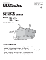
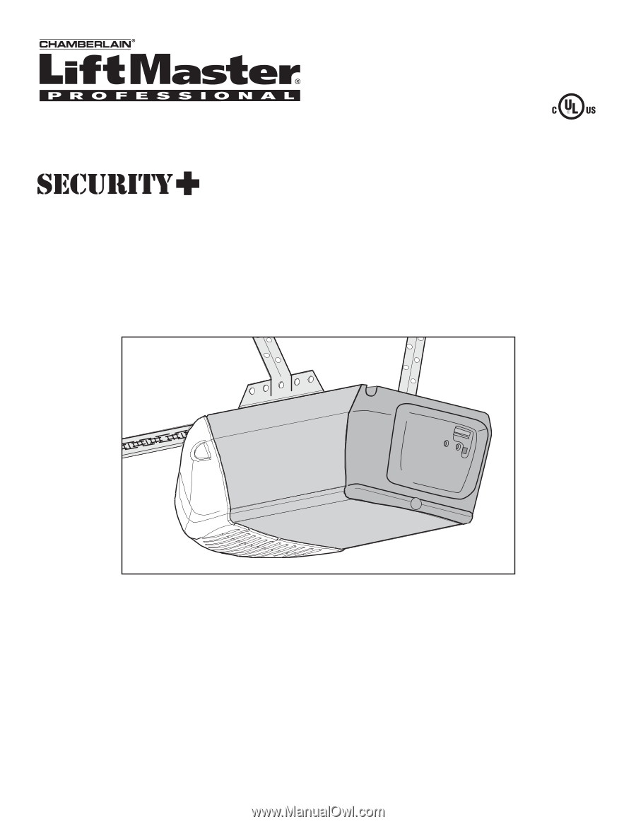
OPENER Models 3245 1/3 HP 3255 1/2 HP 3255-2 1/2 HP For Residential Use Only The Chamberlain Group, Inc. 845 Larch Avenue Elmhurst, Illinois 60126-1196 www.liftmaster.com Owner's Manual ■ Please read this manual and the enclosed safety materials carefully! ■ Fasten the manual near the garage door - LiftMaster 3245 | 3255 Manual - Page 2
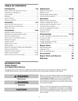
To add, reprogram or change a Keyless Entry PIN 32 Repair Parts 33-34 Rail assembly parts 33 Installation parts 33 Motor unit assembly parts 34 Accessories 35 Repair Parts and Service 36 Warranty 36 INTRODUCTION Safety Symbol and Signal Word Review This garage door opener has been - LiftMaster 3245 | 3255 Manual - Page 3
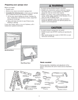
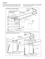
to garage door and opener: • ALWAYS disable locks BEFORE installing and operating the opener. • ONLY operate garage door opener at 120V, 60 Hz to avoid malfunction and damage. Sectional Door One-Piece Door Tools needed During assembly, installation and adjustment of the opener, instructions will - LiftMaster 3245 | 3255 Manual - Page 4
when garage door is closed. FINISHED CEILING Support bracket & fastening hardware is required. See page 12. Motor Unit Wallmounted Door Control Access Door ONE-PIECE DOOR WITH TRACK Slack in chain tension is normal when garage door is closed. Access Door Safety Reversing Sensor Gap between - LiftMaster 3245 | 3255 Manual - Page 5
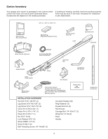
Inventory Your garage door opener is packaged in two cartons which If anything is missing, carefully check the packing material. contain the motor unit and all parts illustrated below. Parts may be stuck in the foam. Hardware for installation Accessories will depend on the model purchased. is - LiftMaster 3245 | 3255 Manual - Page 6
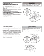
ASSEMBLY STEP 1 Attach the Rail to the Motor Unit To avoid installation difficulties, do not run the garage door opener until instructed to do so. • Remove the two washered bolts mounted in top of motor unit. • Position rail at a 45˚ angle to opener so one hole in rail and motor unit line up. • - LiftMaster 3245 | 3255 Manual - Page 7
chain if necessary. Then repeat Adjustment Step 3. Base of Rail Mid Length of Rail You have now finished assembling your garage door opener. Please read the following warnings before proceeding to the installation section. INSTALLATION WARNING IMPORTANT INSTALLATION INSTRUCTIONS WARNING - LiftMaster 3245 | 3255 Manual - Page 8
CEILING MOUNT FOR HEADER BRACKET Structural Supports Level (optional) Installation procedures vary according to garage door types. Follow the instructions which apply to your door. 1. Close the door and mark the inside vertical centerline of the garage door. 2. Extend the line onto the header - LiftMaster 3245 | 3255 Manual - Page 9
attach the header bracket either to the wall above the garage door, or to the ceiling. Follow the instructions which will work best for your particular requirements. Do not install the header bracket over drywall. If installing into masonry, use concrete anchors (not provided). WALL HEADER BRACKET - LiftMaster 3245 | 3255 Manual - Page 10
Bracket INSTALLATION STEP 3 Attach the Rail to the Header Bracket • Position the opener on the garage floor below the header bracket. Use packing material as a protective base. NOTE: If the door spring is in the way you'll need help. Have someone hold the opener securely on a temporary support to - LiftMaster 3245 | 3255 Manual - Page 11
outer sections. Slide the outer trolley toward the motor unit. The trolley can remain disconnected until Installation Step 12 is completed. To prevent damage to garage door, rest garage door opener rail on 2x4 placed on top section of door. Rail Door 2x4 is used to determine the correct mounting - LiftMaster 3245 | 3255 Manual - Page 12
where the trolley slides with rail grease. NOTE: DO NOT connect power to opener at this time. To avoid possible SERIOUS INJURY from a falling garage door opener, fasten it SECURELY to structural supports of the garage. Concrete anchors MUST be used if installing any brackets into masonry. Figure - LiftMaster 3245 | 3255 Manual - Page 13
Sensor Instructions beginning on page 16. To prevent possible SERIOUS INJURY or DEATH from electrocution: • Be sure power is NOT connected BEFORE installing door control. • Connect ONLY to 24 VOLT low voltage wires. To prevent possible SERIOUS INJURY or DEATH from a closing garage door: • Install - LiftMaster 3245 | 3255 Manual - Page 14
Use A19, standard neck garage door opener bulbs for replacement. NOTE INSTALLATION STEP 8 Attach the Emergency Release Rope and Handle • Thread one end of the rope through the hole in the top of the red handle so "NOTICE" reads right side up as shown. Secure with an overhand knot at least 1" (2.5 cm - LiftMaster 3245 | 3255 Manual - Page 15
or DEATH from electrocution or fire: • Be sure power is not connected to the opener, and disconnect power to circuit BEFORE removing cover to establish permanent wiring connection. • Garage door installation and wiring MUST be in compliance with ALL local electrical and building codes. • NEVER - LiftMaster 3245 | 3255 Manual - Page 16
opener BEFORE installing the safety reversing sensor. To prevent SERIOUS INJURY or DEATH from a closing garage door: • Correctly connect and align the safety reversing sensor. This required safety device MUST NOT be disabled. • Install the safety reversing sensor so beam is NO HIGHER than 6" (15 cm - LiftMaster 3245 | 3255 Manual - Page 17
sure power to the opener is disconnected. Install and align the brackets so the sensors will face each other across the garage door, with the beam no higher than 6" (15 cm) above the floor. They may be installed in one of three ways, as follows. Garage door track installation (preferred): • Slip the - LiftMaster 3245 | 3255 Manual - Page 18
the wing nut. Figure 5 Wing Nut 1/4"-20 Carriage Bolt 1/4"-20x1/2" Lens TROUBLESHOOTING THE SAFETY REVERSING SENSORS 1. If the sending eye indicator light does not glow steadily after installation, check for: • Electric power to the opener. • A short in the white or white/black wires. These can - LiftMaster 3245 | 3255 Manual - Page 19
of angle iron are used to create a U-shaped support. The best solution is to check with your garage door manufacturer for an opener installation door reinforcement kit. NOTE: Many door reinforcement kits provide for direct attachment of the clevis pin and door arm. In this case you will not need the - LiftMaster 3245 | 3255 Manual - Page 20
for your installation. (Refer to the dotted line optional placement drawing.) HARDWARE SHOWN ACTUAL SIZE Self-Threading Screw 1/4"-14x5/8" Header Wall 2x4 Support Finished Ceiling Header Bracket Door Bracket Optional Placement of Door Bracket Vertical Centerline of Garage Door HORIZONTAL AND - LiftMaster 3245 | 3255 Manual - Page 21
INSTALLATION STEP 12 Connect Door Arm to Trolley Follow instructions which apply to your door type as illustrated below and on the following page. SECTIONAL DOORS ONLY • Make sure garage door arm. Cut about 6" (15 cm) from the solid end. Reconnect release handle toward the opener at a 45° angle - LiftMaster 3245 | 3255 Manual - Page 22
Door Control push button. The trolley will travel to the fully open position. - Manually raise the door to the open position (parallel to the floor), and lift the door One full turn equals 2" (5 cm) of trolley travel. 3. Connect the door arm to the trolley: • Close the door and join the curved arm to - LiftMaster 3245 | 3255 Manual - Page 23
travel cycle: If the opener lights are flashing, the Safety Reversing Sensors are either not installed, misaligned, or obstructed. See Troubleshooting, page 18. Test the door for binding: Pull the emergency release handle. Manually open and close the door. If the door is binding or unbalanced, call - LiftMaster 3245 | 3255 Manual - Page 24
the Force Force adjustment controls are located on the back panel of the motor unit. Force adjustment settings regulate the amount of power required to open and close the door. If the forces are set too light, door travel may be interrupted by nuisance reversals in the down direction and stops - LiftMaster 3245 | 3255 Manual - Page 25
carton in the path of the door. • Press the remote control push button to close the door. The door will not move more than an inch (2.5 cm), and the opener lights will flash. The garage door opener will not close from a remote if the indicator light in either sensor is off (alerting you to the - LiftMaster 3245 | 3255 Manual - Page 26
systems technician. 14. ALWAYS disconnect electric power to garage door opener BEFORE making any repairs or removing covers. 15. SAVE THESE INSTRUCTIONS. Using Your Garage Door Opener Your Security✚® opener and hand-held remote control have been factory-set to a matching code which changes with - LiftMaster 3245 | 3255 Manual - Page 27
on the motor unit panel is activated. To prevent possible SERIOUS INJURY or DEATH from a falling garage door: • If possible, use emergency release handle to disengage trolley ONLY when garage door is CLOSED. Weak or broken springs or unbalanced door could result in an open door falling rapidly - LiftMaster 3245 | 3255 Manual - Page 28
the instructions carefully. Repeat the safety reverse test (Adjustment Step 3, page 25) after any adjustment of limits or force. MAINTENANCE SCHEDULE Once a Month • Manually operate door. If it is unbalanced or binding, call a trained door systems technician. • Check to be sure door opens and - LiftMaster 3245 | 3255 Manual - Page 29
HAVING A PROBLEM? 1. My door will not close and the light bulbs blink on my motor unit: The safety reversing sensor must be connected and aligned correctly before the garage door opener will move in the down direction. • Verify the safety sensors are properly installed, aligned and free of any - LiftMaster 3245 | 3255 Manual - Page 30
5 times and motor unit moves 6-8" (15-20 cm), replace RPM sensor. • If motor unit doesn't operate, motor unit is overheated. Wait 30 minutes and retry. If motor unit still will not operate replace logic board. Symptom: Motor unit doesn't operate. • Replace logic board because motor rarely fails. 30 - LiftMaster 3245 | 3255 Manual - Page 31
. Below are instructions for programming your opener to operate with additional Security✚® remote controls. To Add or Reprogram a Hand-held Remote Control USING THE "LEARN" BUTTON USING THE MULTI-FUNCTION DOOR CONTROL LOCK LIGHT 1. Press and release the "learn" button on the motor unit. The - LiftMaster 3245 | 3255 Manual - Page 32
To Add, Reprogram or Change a Keyless Entry PIN NOTE: Your new Keyless Entry must be programmed to operate your garage door opener. USING THE "LEARN" BUTTON USING THE MULTI-FUNCTION DOOR CONTROL LOCK LIGHT 1. Press and release the "learn" button on motor unit. The learn indicator light will - LiftMaster 3245 | 3255 Manual - Page 33
REPAIR PARTS Rail Assembly Parts 5 1 3 4 2 Installation Parts KEY PART NO. NO. DESCRIPTION 1 4A1008 Master link kit 6 2 41A4813 Chain pulley bracket 3 41A3489 Complete trolley assembly 4 1707LM One-piece rail 7' (2.1 m) 1708LM One-piece rail 8' (2.4 m) 1710LM One-piece rail 10' (3 - LiftMaster 3245 | 3255 Manual - Page 34
Interrupter cup assembly RPM sensor assembly Receiver logic board assy. Complete with: Logic board and end panel with all labels Low voltage wire harness assy. High voltage wire harness assy. End panel with all labels NOT SHOWN Motor shaft bearing kit Opener assembly hardware kit (includes screws - LiftMaster 3245 | 3255 Manual - Page 35
ACCESSORIES 1702LM 41A5281 Outside Quick Release: Required for a garage with NO access door. Enables homeowner to open garage door manually from outside by disengaging trolley. 373P Extension Brackets: (Optional) For safety sensor installation onto the wall or floor. 374LM 377LM 915LM CLOSED - LiftMaster 3245 | 3255 Manual - Page 36
OUR TOLL FREE NUMBER: 1-800-528-9131 www.liftmaster.com For professional installation, parts and service, contact your local LIFTMASTER/CHAMBERLAIN dealer. Look for him in the Yellow Pages, or call our Service number for a list of dealers in your area. Selling prices will be furnished on request or
-
 1
1 -
 2
2 -
 3
3 -
 4
4 -
 5
5 -
 6
6 -
 7
7 -
8
-
9
-
10
-
11
-
12
-
13
-
14
-
15
-
16
-
17
-
18
-
19
-
20
-
21
-
22
-
23
-
24
-
25
-
26
-
27
-
28
-
29
-
30
-
31
-
32
-
33
-
34
-
35
-
36
 |
 |
The Chamberlain Group, Inc.
845 Larch Avenue
Elmhurst, Illinois 60126-1196
www.liftmaster.com
GARAGE DOOR OPENER
Models 3245 1/3 HP
3255 1/2 HP
3255-2 1/2 HP
For Residential Use Only
Owner’s Manual
■
Please read this manual and the enclosed safety materials carefully!
■
Fasten the manual near the garage door after installation.
■
The door WILL NOT CLOSE unless the Protector System
®
is connected and properly
aligned.
■
Periodic checks of the opener are required to ensure safe operation.
■
The model number label is located on the front panel of your opener.
®