LiftMaster 3255 3255 Manual
LiftMaster 3255 Manual
 |
View all LiftMaster 3255 manuals
Add to My Manuals
Save this manual to your list of manuals |
LiftMaster 3255 manual content summary:
- LiftMaster 3255 | 3255 Manual - Page 1
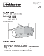
1/3 HP 3255 1/2 HP 3255-2 1/2 HP For Residential Use Only The Chamberlain Group, Inc. 845 Larch Avenue Elmhurst, Illinois 60126-1196 www.liftmaster.com Owner's Manual ■ Please read this manual and the enclosed safety materials carefully! ■ Fasten the manual near the garage door after installation - LiftMaster 3255 | 3255 Manual - Page 2
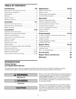
3-Button remotes 31 To add, reprogram or change a Keyless Entry PIN 32 Repair Parts 33-34 Rail assembly parts 33 Installation parts 33 Motor unit assembly parts 34 Accessories 35 Repair Parts and Service 36 Warranty 36 INTRODUCTION Safety Symbol and Signal Word Review This garage - LiftMaster 3255 | 3255 Manual - Page 3
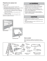
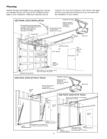
to garage door and opener: • ALWAYS disable locks BEFORE installing and operating the opener. • ONLY operate garage door opener at 120V, 60 Hz to avoid malfunction and damage. Sectional Door One-Piece Door Tools needed During assembly, installation and adjustment of the opener, instructions will - LiftMaster 3255 | 3255 Manual - Page 4
CEILING Support bracket & fastening hardware is required. See page 12. Slack in chain tension is normal when garage door is closed. Motor Unit Vertical Centerline of Garage Door Extension Spring OR Torsion Spring Wallmounted Door Control Access Door --- --- -- Safety Reversing Sensor Safety - LiftMaster 3255 | 3255 Manual - Page 5
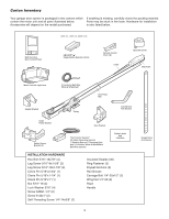
unit and all parts illustrated below. Parts may be stuck in the foam. Hardware for installation Accessories will depend on the model purchased. is also listed below. 3245 (1), 3255 (1), 3255-2 (2) LOCK LIGHT Multi-Function Door Control Panel : SECURITY ® Single-Button Remote Control Remote - LiftMaster 3255 | 3255 Manual - Page 6
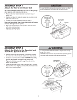
Motor Unit To avoid installation difficulties, do not run the garage door opener until instructed to do so. • Remove the two washered bolts mounted in top of motor unit. • Position rail at a 45˚ angle to opener so one hole in rail and motor unit line up. • Thread one of the washered bolts part way - LiftMaster 3255 | 3255 Manual - Page 7
connect garage door opener to power source until instructed to do so. 8. NEVER wear watches, rings or loose clothing while installing or servicing opener. They could be caught in garage door or opener mechanisms. 9. Install wall-mounted garage door control: • within sight of the garage door. • out - LiftMaster 3255 | 3255 Manual - Page 8
CEILING MOUNT FOR HEADER BRACKET Structural Supports Level (optional) Installation procedures vary according to garage door types. Follow the instructions which apply to your door. 1. Close the door and mark the inside vertical centerline of the garage door. 2. Extend the line onto the header - LiftMaster 3255 | 3255 Manual - Page 9
attach the header bracket either to the wall above the garage door, or to the ceiling. Follow the instructions which will work best for your particular requirements. Do not install the header bracket over drywall. If installing into masonry, use concrete anchors (not provided). WALL HEADER BRACKET - LiftMaster 3255 | 3255 Manual - Page 10
Bracket INSTALLATION STEP 3 Attach the Rail to the Header Bracket • Position the opener on the garage floor below the header bracket. Use packing material as a protective base. NOTE: If the door spring is in the way you'll need help. Have someone hold the opener securely on a temporary support to - LiftMaster 3255 | 3255 Manual - Page 11
outer sections. Slide the outer trolley toward the motor unit. The trolley can remain disconnected until Installation Step 12 is completed. To prevent damage to garage door, rest garage door opener rail on 2x4 placed on top section of door. Rail Door 2x4 is used to determine the correct mounting - LiftMaster 3255 | 3255 Manual - Page 12
where the trolley slides with rail grease. NOTE: DO NOT connect power to opener at this time. To avoid possible SERIOUS INJURY from a falling garage door opener, fasten it SECURELY to structural supports of the garage. Concrete anchors MUST be used if installing any brackets into masonry. Figure - LiftMaster 3255 | 3255 Manual - Page 13
from a closing garage door: • Install door control within sight of garage door, out of reach of children at a minimum height of 5 feet (1.5 m), and away from ALL moving parts of door. • NEVER permit children to operate or play with door control push buttons or remote control transmitters. • Activate - LiftMaster 3255 | 3255 Manual - Page 14
will turn ON and remain lit for approximately 4-1/2 minutes when power is connected. Then the lights will turn OFF. • Reverse the procedure to close the lens. • Use A19, standard neck garage door opener bulbs for replacement. NOTE: Use only standard light bulbs. The use of short neck or speciality - LiftMaster 3255 | 3255 Manual - Page 15
possible SERIOUS INJURY or DEATH from electrocution or fire: • Be sure power is not connected to the opener, and disconnect power to circuit BEFORE removing cover to establish permanent wiring connection. • Garage door installation and wiring MUST be in compliance with ALL local electrical and - LiftMaster 3255 | 3255 Manual - Page 16
(see Accessories) are available if needed. If installing in masonry construction, add a piece of wood at each location to avoid drilling extra holes in masonry if repositioning is necessary. The invisible light beam path must be unobstructed. No part of the garage door (or door tracks, springs - LiftMaster 3255 | 3255 Manual - Page 17
Be sure power to the opener is disconnected. Install and align the brackets so the sensors will face each other across the garage door, with the beam no higher than 6" (15 cm) above the floor. They may be installed in one of three ways, as follows. Garage door track installation (preferred): • Slip - LiftMaster 3255 | 3255 Manual - Page 18
the wing nut. Figure 5 Wing Nut 1/4"-20 Carriage Bolt 1/4"-20x1/2" Lens TROUBLESHOOTING THE SAFETY REVERSING SENSORS 1. If the sending eye indicator light does not glow steadily after installation, check for: • Electric power to the opener. • A short in the white or white/black wires. These can - LiftMaster 3255 | 3255 Manual - Page 19
of angle iron are used to create a U-shaped support. The best solution is to check with your garage door manufacturer for an opener installation door reinforcement kit. NOTE: Many door reinforcement kits provide for direct attachment of the clevis pin and door arm. In this case you will not need the - LiftMaster 3255 | 3255 Manual - Page 20
for your installation. (Refer to the dotted line optional placement drawing.) HARDWARE SHOWN ACTUAL SIZE Self-Threading Screw 1/4"-14x5/8" Header Wall 2x4 Support Finished Ceiling Header Bracket Door Bracket Optional Placement of Door Bracket Vertical Centerline of Garage Door HORIZONTAL AND - LiftMaster 3255 | 3255 Manual - Page 21
INSTALLATION STEP 12 Connect Door Arm to Trolley Follow instructions which apply to your door type as illustrated below and on the following page. SECTIONAL DOORS ONLY • Make sure garage door about 6" (15 cm) from the solid lock washers and nuts. • Pull the emergency release handle toward the opener - LiftMaster 3255 | 3255 Manual - Page 22
Turn the UP limit adjustment screw counter-clockwise 4 turns. - Press the Door Control push button. The trolley will travel to the fully open position. - Manually raise the door to the open position (parallel to the floor), and lift the door arm to the trolley. The arm should touch the trolley just - LiftMaster 3255 | 3255 Manual - Page 23
travel cycle: If the opener lights are flashing, the Safety Reversing Sensors are either not installed, misaligned, or obstructed. See Troubleshooting, page 18. Test the door for binding: Pull the emergency release handle. Manually open and close the door. If the door is binding or unbalanced, call - LiftMaster 3255 | 3255 Manual - Page 24
ADJUSTMENT STEP 2 Adjust the Force Force adjustment controls are located on the back panel of the motor unit. Force adjustment settings regulate the amount of power required to open and close the door. If the forces are set too light, door travel may be interrupted by nuisance reversals in the down - LiftMaster 3255 | 3255 Manual - Page 25
the remote control push button to open the door. • Place the opener carton in the path of the door. • Press the remote control push button to close the door. The door will not move more than an inch (2.5 cm), and the opener lights will flash. The garage door opener will not close from a remote if - LiftMaster 3255 | 3255 Manual - Page 26
mounted Door Control: Hold the push button or bar down until the door starts to move. • The Keyless Entry (See Accessories): If provided with your garage door opener, it must be programmed before use. See Programming. When the opener is activated (with the safety reversing sensor correctly installed - LiftMaster 3255 | 3255 Manual - Page 27
Designed to prevent operation of the door from hand-held remote controls. However, the door will open and close from the Door Control, the Outside Keylock and the Keyless Entry Accessories. To activate, press and hold the Lock button for 2 seconds. The push bar light will flash as long as the - LiftMaster 3255 | 3255 Manual - Page 28
CONTROLS screwdriver is required. Follow the instructions carefully. Repeat the safety reverse test (Adjustment Step 3, page 25) after any adjustment of limits or force. MAINTENANCE SCHEDULE Once a Month • Manually operate door or replacing the battery. THERE ARE NO OTHER USER SERVICEABLE PARTS. - LiftMaster 3255 | 3255 Manual - Page 29
instructions. Refer to Programming. • If remote will still not activate your door, check diagnostic LED for flashes on motor unit then refer to Diagnostic Chart on the following page. Bell Wire Safety Reversing Sensor Sending Eye Safety Reversing Sensor (Amber Indicator Light) "Learn" Button - LiftMaster 3255 | 3255 Manual - Page 30
FLASHES Door control or wire shorted. 4 FLASHES Safety Reversing Sensors slightly misaligned (dim or flashing LED). 5 FLASHES Motor overheated or possible RPM sensor failure. Unplug to reset. 6 FLASHES Motor Circuit Failure. Replace Receiver Logic Board. Symptom: One or both of the Indicator lights - LiftMaster 3255 | 3255 Manual - Page 31
for programming your opener to operate with additional Security✚® remote controls. To Add or Reprogram a Hand-held Remote Control USING THE "LEARN" BUTTON USING THE MULTI-FUNCTION DOOR CONTROL LOCK LIGHT 1. Press and release the "learn" button on the motor unit. The learn indicator light will - LiftMaster 3255 | 3255 Manual - Page 32
PIN NOTE: Your new Keyless Entry must be programmed to operate your garage door opener. USING THE "LEARN" BUTTON USING THE MULTI-FUNCTION DOOR CONTROL LOCK LIGHT 1. Press and release the "learn" button on motor unit. The learn indicator light will glow steadily for 30 seconds. 2. Within 30 - LiftMaster 3255 | 3255 Manual - Page 33
rail 8' (2.4 m) 1710LM One-piece rail 10' (3 m) 5 41D3484 Full chain assembly 6 83A11-2 Rail grease 1 LOCK LIGHT 3 2 4 5 7 CEILING MOUNT ONLY UP NOTICE 6 10 11 12 8 9 KEY PART NO. NO. DESCRIPTION 1 41A5273-1 Multi-function door control panel 2 371LM 1 Button remote control - LiftMaster 3255 | 3255 Manual - Page 34
drive and retainer Limit switch assembly Interrupter cup assembly RPM sensor assembly Receiver logic board assy. Complete with: Logic board and end panel with all labels Low voltage wire harness assy. High voltage wire harness assy. End panel with all labels NOT SHOWN Motor shaft bearing kit Opener - LiftMaster 3255 | 3255 Manual - Page 35
, light feature and auxiliary button. Includes battery. Laser Park Assist: Laser enables homeowners to precisely park vehicles in the garage. Surge Protector: The Garage Door Opener Surge Protector is designed to protect LiftMaster® garage door openers against damage from lightning and power surges - LiftMaster 3255 | 3255 Manual - Page 36
REPAIRED OR REPLACED UNIT, REPLACEMENT OF BATTERIES AND LIGHT BULBS OR UNITS INSTALLED FOR NON-RESIDENTIAL USE. THIS LIMITED WARRANTY DOES NOT COVER ANY PROBLEMS WITH, OR RELATING TO, THE GARAGE DOOR OR GARAGE DOOR HARDWARE, INCLUDING BUT NOT LIMITED TO THE DOOR SPRINGS, DOOR ROLLERS, DOOR ALIGNMENT
-
 1
1 -
 2
2 -
 3
3 -
 4
4 -
 5
5 -
 6
6 -
 7
7 -
8
-
9
-
10
-
11
-
12
-
13
-
14
-
15
-
16
-
17
-
18
-
19
-
20
-
21
-
22
-
23
-
24
-
25
-
26
-
27
-
28
-
29
-
30
-
31
-
32
-
33
-
34
-
35
-
36
 |
 |
The Chamberlain Group, Inc.
845 Larch Avenue
Elmhurst, Illinois 60126-1196
www.liftmaster.com
GARAGE DOOR OPENER
Models 3245 1/3 HP
3255 1/2 HP
3255-2 1/2 HP
For Residential Use Only
Owner’s Manual
■
Please read this manual and the enclosed safety materials carefully!
■
Fasten the manual near the garage door after installation.
■
The door WILL NOT CLOSE unless the Protector System
®
is connected and properly
aligned.
■
Periodic checks of the opener are required to ensure safe operation.
■
The model number label is located on the front panel of your opener.
®