LiftMaster 3585 3585 Elite Series Manual
LiftMaster 3585 Manual
 |
View all LiftMaster 3585 manuals
Add to My Manuals
Save this manual to your list of manuals |
LiftMaster 3585 manual content summary:
- LiftMaster 3585 | 3585 Elite Series Manual - Page 1
® GARAGE DOOR OPENER Model 3585 3/4 HP For Residential Use Only The Chamberlain Group, Inc. 845 Larch Avenue Elmhurst, Illinois 60126-1196 www.liftmaster.com Owner's Manual ■ Please read this manual and the enclosed safety materials carefully! ■ Fasten the manual near the garage door after - LiftMaster 3585 | 3585 Elite Series Manual - Page 2
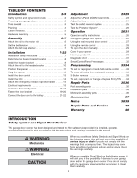
or change a Keyless Entry PIN . . . .34 Repair Parts 35-36 Rail assembly parts 35 Installation parts 35 Motor unit assembly parts 36 Accessories 37 Notes 38-39 Repair Parts and Service 40 Warranty 40 INTRODUCTION Safety Symbol and Signal Word Review This garage door opener has been - LiftMaster 3585 | 3585 Elite Series Manual - Page 3
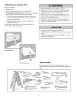
to garage door and opener: • ALWAYS disable locks BEFORE installing and operating the opener. • ONLY operate garage door opener at 120V, 60 Hz to avoid malfunction and damage. Sectional Door One-Piece Door Tools needed During assembly, installation and adjustment of the opener, instructions will - LiftMaster 3585 | 3585 Elite Series Manual - Page 4
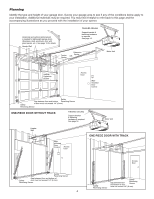
as you proceed with the installation of your opener. Horizontal and vertical reinforcement is needed for lightweight garage doors (fiberglass, steel, aluminum, door with glass panels, etc.). See page 19 for details. Header Wall FINISHED CEILING Support bracket & fastening hardware is required - LiftMaster 3585 | 3585 Elite Series Manual - Page 5
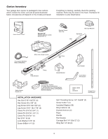
for installation is also listed below. LOCK LIGHT SmLCarDt CMoontitoronl DPeatneecltTMing Door Control Console SECURITY✚® 3-Button Remote Control Model 373P (1) Remote Control TVrisaonrsmCliitpter Visor Clip Belt Belt Cap Retainer Styrofoam 2-Conductor Bell Wire White & White/Red Motor Unit - LiftMaster 3585 | 3585 Elite Series Manual - Page 6
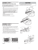
ASSEMBLY STEP 1 Attach the Rail to the Motor Unit To avoid installation difficulties, do not run the garage door opener until instructed to do so. • Remove the bolt and lock nut from the top of the motor unit. • Place rail onto the bolt mounted on the motor unit and align the back hole with the - LiftMaster 3585 | 3585 Elite Series Manual - Page 7
moving garage door opener: • ALWAYS keep hand clear of sprocket while operating opener. • Securely attach sprocket cover BEFORE operating. Hex Screws 8x3/8" Belt Cap Retainer Motor Unit Sprocket Mounting Plate Hex Screw #8x3/8" INSTALLATION WARNING IMPORTANT INSTALLATION INSTRUCTIONS WARNING - LiftMaster 3585 | 3585 Elite Series Manual - Page 8
CEILING MOUNT FOR HEADER BRACKET Structural Supports Level (optional) Installation procedures vary according to garage door types. Follow the instructions which apply to your door. 1. Close the door and mark the inside vertical centerline of the garage door. 2. Extend the line onto the header - LiftMaster 3585 | 3585 Elite Series Manual - Page 9
attach the header bracket either to the wall above the garage door, or to the ceiling. Follow the instructions which will work best for your particular requirements. Do not install the header bracket over drywall. If installing into masonry, use concrete anchors (not provided). WALL HEADER BRACKET - LiftMaster 3585 | 3585 Elite Series Manual - Page 10
header bracket. • Align the bracket holes and join with a clevis pin as shown. • Insert a ring fastener to secure. Garage Door Header Bracket Ring Fastener Clevis Pin 5/16"x2-3/4" Belt Pulley Bracket Rail Temporary Support HARDWARE SHOWN ACTUAL SIZE Clevis Pin 5/16"x2-3/4" 10 Ring Fastener - LiftMaster 3585 | 3585 Elite Series Manual - Page 11
outer sections. Slide the outer trolley toward the motor unit. The trolley can remain disconnected until Installation Step 12 is completed. To prevent damage to garage door, rest garage door opener rail on 2x4 placed on top section of door. Rail Door 2x4 is used to determine the correct mounting - LiftMaster 3585 | 3585 Elite Series Manual - Page 12
at this time. To avoid possible SERIOUS INJURY from a falling garage door opener, fasten it SECURELY to structural supports of the garage. Concrete anchors MUST be used if installing any brackets into masonry. Figure 1 Measure Distance Bolt 5/16"-18x7/8" Lock Washer 5/16" Nut 5/16"-18 Structural - LiftMaster 3585 | 3585 Elite Series Manual - Page 13
are desired to operate the same garage door opener, it is recommended to use model 378LM wireless wall control as the secondary control console. 1. Strip 7/16" (11 mm) of insulation from one end of bell wire and connect to the two screw terminals on back of door control by color: white wire to the - LiftMaster 3585 | 3585 Elite Series Manual - Page 14
downward until the lens hinge is in the fully open position. Do not remove the lens. • Install a 100 watt maximum light bulb in each socket. Light bulb procedure to close the lens. • Use A19, standard neck garage door opener bulbs for replacement. NOTE: Use only standard light bulbs. The use of - LiftMaster 3585 | 3585 Elite Series Manual - Page 15
or DEATH from electrocution or fire: • Be sure power is not connected to the opener, and disconnect power to circuit BEFORE removing cover to establish permanent wiring connection. • Garage door installation and wiring MUST be in compliance with all local electrical and building codes. • NEVER - LiftMaster 3585 | 3585 Elite Series Manual - Page 16
) are available if needed. If installing in masonry construction, add a piece of wood at each location to avoid drilling extra holes in masonry if repositioning is necessary. The invisible light beam path must be unobstructed. No part of the garage door (or door tracks, springs, hinges, rollers or - LiftMaster 3585 | 3585 Elite Series Manual - Page 17
higher than 6" (15 cm) above the floor. They may be installed in one of three ways, as follows. Garage door track installation (preferred): • Slip the curved arms over the rounded edge of each door track, with the curved arms facing the door. Snap into place against the side of the track. It should - LiftMaster 3585 | 3585 Elite Series Manual - Page 18
will reverse. If the door is already open, it will not close. The opener lights will blink 10 times. See page 16. Figure 6 Connect Wire to Opener Quick-Connect Terminals Bell Wire Finished Ceiling Bell Wire 1. Strip wire 7/16" (11 mm) 7/16" (11 mm) 2. Twist like colored wires together 3. To - LiftMaster 3585 | 3585 Elite Series Manual - Page 19
brace. For the vertical brace, 2 pieces of angle iron are used to create a U-shaped support. The best solution is to check with your garage door manufacturer for an opener installation door reinforcement kit. NOTE: Many door reinforcement kits provide for direct attachment of the clevis pin and - LiftMaster 3585 | 3585 Elite Series Manual - Page 20
for your installation. (Refer to the dotted line optional placement drawing.) HARDWARE SHOWN ACTUAL SIZE Self-Threading Screw 1/4"-14x5/8" Header Wall 2x4 Support Finished Ceiling Header Bracket Door Bracket Optional Placement of Door Bracket Vertical Centerline of Garage Door HORIZONTAL AND - LiftMaster 3585 | 3585 Elite Series Manual - Page 21
INSTALLATION STEP 12 Connect Door Arm to Trolley Follow instructions which apply to your door type as illustrated below and on the following page. SECTIONAL DOORS ONLY Make sure garage door is fully closed. Pull the emergency release handle to disconnect the outer trolley from the inner trolley. - LiftMaster 3585 | 3585 Elite Series Manual - Page 22
Turn the UP limit adjustment screw counter-clockwise 4 turns. - Press the door control push button. The trolley will travel to the fully open position. - Manually raise the door to the open position (parallel to the floor), and lift the door arm to the trolley. The arm should touch the trolley just - LiftMaster 3585 | 3585 Elite Series Manual - Page 23
Sensors are either not installed, misaligned, or obstructed. See Troubleshooting, page 18. Test the door for binding: Pull the emergency release handle. Manually open and close the door. If the door is binding or unbalanced, call for a trained door systems technician. If the door is balanced and not - LiftMaster 3585 | 3585 Elite Series Manual - Page 24
downward travel (including binding or unbalanced doors), it will reverse. Without a properly installed safety reversal system, persons (particularly small children) could be SERIOUSLY INJURED or KILLED by a closing garage door. • Too much force on garage door will interfere with proper operation of - LiftMaster 3585 | 3585 Elite Series Manual - Page 25
) on the floor. 1-1/2" (3.8 cm) board (or a 2x4 laid flat) ADJUSTMENT STEP 4 Test The Protector System® • Press the remote control push button to open the door. • Place the opener carton in the path of the door. • Press the remote control push button to close the door. The door will not move more - LiftMaster 3585 | 3585 Elite Series Manual - Page 26
and one Security✚® Keyless Entry System. If you purchase a new remote, or if you wish to deactivate any remote, follow the instructions in the Programming section. Activate your opener with any of the following: • The hand-held Remote Control: Hold the large push button down until the door starts to - LiftMaster 3585 | 3585 Elite Series Manual - Page 27
open and close from the Door Control, the Outdoor Key Switch and the Keyless Entry Accessories. To activate, press and hold the Lock button for 2 seconds. To turn off, press and hold the Lock button again for 2 seconds. The Lock feature will also turn off whenever the "learn" button on the motor - LiftMaster 3585 | 3585 Elite Series Manual - Page 28
the remote push button. The opener lights should turn on or off but the door should not move. Troubleshooting PROBLEM SOLUTION Check if proximity lighting is disabled by pressing a button. To prevent possible SERIOUS INJURY or DEATH: • NEVER allow small children near batteries. • If battery is - LiftMaster 3585 | 3585 Elite Series Manual - Page 29
To Open the Door Manually To prevent possible SERIOUS INJURY or DEATH from a falling garage door: • If possible, use emergency release handle to disengage trolley ONLY when garage door is CLOSED. Weak or broken springs or unbalanced door could result in an open door falling rapidly and/or - LiftMaster 3585 | 3585 Elite Series Manual - Page 30
the programming instructions. Refer to Programming. • If remote will still not activate your door, check diagnostic LED for flashes on motor unit then refer to Diagnostic Chart on the following page. Bell Wire 9 1 7 3 5 KG 9 1 7 3 5 KG Safety Reversing Sensor "Learn" Button LED or - LiftMaster 3585 | 3585 Elite Series Manual - Page 31
Located On 9 1 9 1 7 3 7 3 5 5 KG KG Motor Unit Safety Reversing Sensor "Learn" Button LED or Diagnostic LED Diagnostic Chart Installed Safety Reversing Sensor Your garage door opener is programmed with self-diagnostic capabilities. The "Learn" button/diagnostic LED will flash - LiftMaster 3585 | 3585 Elite Series Manual - Page 32
of the unit: Message SAFETY SENSORS CHECK ALIGNMENT, BLOCKAGE OR MISWIRING. SEE OWNER'S MANUAL. Message SAFETY SENSORS MALFUNCTION. CHECK MISWIRING. SEE OWNER'S MANUAL. Message LEARN REMOTE CONTROL. PRESS LEARN BUTTON TO CONFIRM. Meaning: This message will appear if the Safety Reversing Sensors - LiftMaster 3585 | 3585 Elite Series Manual - Page 33
and hold the "learn" button on motor unit until the learn indicator light goes out (approximately 6 seconds). All previous codes are now erased. Reprogram each remote or keyless entry you wish to use. *3-Button Remotes If provided with your garage door opener, the large button is factory programmed - LiftMaster 3585 | 3585 Elite Series Manual - Page 34
To Add, Reprogram or Change a Keyless Entry PIN NOTE: Your new Keyless Entry must be programmed to operate your garage door opener. USING THE "LEARN" BUTTON USING THE SMART CONTROL PANELTM 1. Press and release the "learn" button on motor unit. The learn indicator light will glow steadily for 30 - LiftMaster 3585 | 3585 Elite Series Manual - Page 35
178B35 41A5266-1 Smart Control PanelTM 3-Button remote control 3V2016 Lithium battery: LED and opener 3V2016 Lithium battery: proximity switch Remote control visor clip Emergency release rope and handle assembly 2-Conductor bell wire, white & white/red Door bracket w/clevis pin & fastener Header - LiftMaster 3585 | 3585 Elite Series Manual - Page 36
-1 Capacitor 40uF Resistor Terminal block w/screws 41A2826 41A2825 Universal replacement motor & bracket assembly Complete with: Motor, worm, Interrupter cup assembly RPM sensor assembly Receiver logic board assy. Complete with: Logic board, end panel w/all labels, light socket High voltage wire - LiftMaster 3585 | 3585 Elite Series Manual - Page 37
garage door opener remote or from anywhere in their home with an additional LiftMaster Security✚® remote. Wireless Door Control: Push bar, light feature and auxiliary button. Includes battery. 915LM Garage Door Monitor: Security for the largest door of your home! Tells you if your garage door - LiftMaster 3585 | 3585 Elite Series Manual - Page 38
NOTES 38 - LiftMaster 3585 | 3585 Elite Series Manual - Page 39
NOTES 39 - LiftMaster 3585 | 3585 Elite Series Manual - Page 40
• PART NAME • MODEL NUMBER ADDRESS ORDERS TO: THE CHAMBERLAIN GROUP, INC. Technical Support Group 6050 S. Country Club Road Tucson, Arizona 85706 SERVICE INFORMATION TOLL FREE NUMBER: 1-800-528-9131 LIFTMASTER® GARAGE DOOR OPENER FIVE-YEAR LIMITED WARRANTY LIFETIME MOTOR AND BELT LIMITED WARRANTY
-
 1
1 -
 2
2 -
 3
3 -
 4
4 -
 5
5 -
 6
6 -
 7
7 -
8
-
9
-
10
-
11
-
12
-
13
-
14
-
15
-
16
-
17
-
18
-
19
-
20
-
21
-
22
-
23
-
24
-
25
-
26
-
27
-
28
-
29
-
30
-
31
-
32
-
33
-
34
-
35
-
36
-
37
-
38
-
39
-
40
 |
 |

The Chamberlain Group, Inc.
845 Larch Avenue
Elmhurst, Illinois 60126-1196
www.liftmaster.com
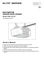
GARAGE DOOR OPENER
Model 3585 3/4 HP
For Residential Use Only
Owner’s Manual
■
Please read this manual and the enclosed safety materials carefully!
■
Fasten the manual near the garage door after installation.
■
The door WILL NOT CLOSE unless the Protector System
®
is connected and properly
aligned.
■
Periodic checks of the opener are required to ensure safe operation.
■
The model number label is located under the light lens on the left side panel of your
opener.
®