LiftMaster 3950 3950 Addendum Manual
LiftMaster 3950 Manual
 |
View all LiftMaster 3950 manuals
Add to My Manuals
Save this manual to your list of manuals |
LiftMaster 3950 manual content summary:
- LiftMaster 3950 | 3950 Addendum Manual - Page 1
INSTRUCTIONS It is important to identify the door type before attempting an installation of the Model 3950 door operator. MOUNTING OPTIONS: 1 Standard wall mount using the brackets included with the operator. 2 Outside bracket mount using the optional mounting bracket Model 3950MB. Inside bracket - LiftMaster 3950 | 3950 Addendum Manual - Page 2
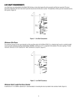
minimum amount of side room depends on the mounting option for the Model 3950. For a standard wall mount or outside bracket mount using the optional mounting bracket Model 3950MB, a minimum of 11" is required to the outside of the door opening. If inside mounted, minimum of 3.75" clearance for "Wall - LiftMaster 3950 | 3950 Addendum Manual - Page 3
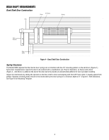
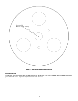
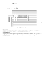
2nd Drum Spring Axle Door Bracket Door Guide Figure 4 - Dead Shaft Door Construction Spring Clearance The Model 3950 requires that the internal door springs do not interfere with the 4.5" mounting pattern on the end drum (Figure 4 ). Some door manufacturers require the door to be ordered with - LiftMaster 3950 | 3950 Addendum Manual - Page 4
Mounting Hole (PEM nut may be present) 2.25" Figure 5 - Drum Holes To Inspect For Obstruction Door Construction The Dead Shaft Door must not have more than a 2" inset from the curtain edge to the drum. The Model 3950 comes with a selection of spacers that can be used in conjunction to provide a - LiftMaster 3950 | 3950 Addendum Manual - Page 5
depends on the mounting option for the Model 3950. For a standard wall mount to the outside of the door opening, a minimum of 11" is required for the operator, however, the door brackets must also be considered if they interfere with operator installation. Dead Shaft Door brackets should be moved - LiftMaster 3950 | 3950 Addendum Manual - Page 6
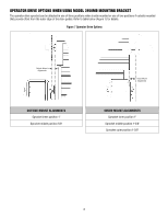
DRIVE OPTIONS WHEN USING MODEL 3950MB MOUNTING BRACKET The operator drive sprocket can be attached in one of three positions when inside mounted or one of two positions if outside mounted that provide offset from the outer edge of the door guides: Refer to table below (Figure 7) for details. Figure - LiftMaster 3950 | 3950 Addendum Manual - Page 7
6.5" 2.25" 1.625" 3.25" .39" holes 120° apart 6.5" Figure 8 - Mounting Hole Template 7 - LiftMaster 3950 | 3950 Addendum Manual - Page 8
01-35863B © 2010, The Chamberlain Group, Inc. All Rights Reserved
-
 1
1 -
 2
2 -
 3
3 -
 4
4 -
 5
5 -
 6
6 -
 7
7 -
8
 |
 |
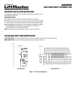
LIVE OR DEAD SHAFT DOOR IDENTIFICATION
LIVE SHAFT DOOR -
The axle rotates with the drum and door assembly when the door is opened or closed.
DEAD SHAFT DOOR -
The axle is locked in place while the door opens and closes.
Figure 1 - Door Type Identification
Rotating Axle
Fixed Axle
1
2
3
Live Shaft Door
Dead Shaft Door
IMPORTANT INSTALLATION INSTRUCTIONS
It is important to identify the door type before attempting an installation of the
Model 3950 door operator.
MOUNTING OPTIONS:
Standard wall mount using the brackets included with the operator.
Outside bracket mount using the optional mounting bracket Model 3950MB.
Inside bracket mount using the optional mounting bracket Model 3950MB.
If standard wall mount brackets are not acceptable for installation, optional
Model 3950MB mounting brackets may be required. To order visit
www.liftmaster.com or contact door supplier.
NOTE:
The inside mounting option takes away from clear door opening.
ADDENDUM
DOOR COMPATIBILITY FOR MODEL 3950