LiftMaster 8355 8355 Manual
LiftMaster 8355 Manual
 |
View all LiftMaster 8355 manuals
Add to My Manuals
Save this manual to your list of manuals |
LiftMaster 8355 manual content summary:
- LiftMaster 8355 | 8355 Manual - Page 1
PREMIUM Series Belt Drive Garage Door Opener Model 8355 - 1/2 hp FOR RESIDENTIAL USE ONLY ■ Please read this manual and the enclosed safety materials carefully! ■ Fasten the manual near the garage door after installation. ■ The door WILL NOT CLOSE unless the Protector System® is connected and - LiftMaster 8355 | 8355 Manual - Page 2
Preparation Safety Symbol and Signal Word Review This garage door opener has been designed and tested to offer safe service provided it is installed, operated, maintained and tested in strict accordance with the instructions and warnings contained in this manual. When you see these Safety Symbols - LiftMaster 8355 | 8355 Manual - Page 3
/black wire attached: Sending Sensor (1) Receiving Sensor (1) and Safety Sensor Brackets (2) O. Safety labels and literature P. Rail grease H L M Not Provided J Not Provided N O P I SECURITY✚ 2.0TM ACCESSORIES 882LM Multi-Function Door Control 893LM Remote Control Hardware Installation Hex - LiftMaster 8355 | 8355 Manual - Page 4
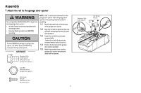
Assembly 1 Attach the rail to the garage door opener To avoid possible SERIOUS INJURY to finger from moving garage door opener: • ALWAYS keep hand clear of sprocket while operating opener. • Securely attach sprocket cover BEFORE operating. To avoid SERIOUS damage to garage door opener, use ONLY - LiftMaster 8355 | 8355 Manual - Page 5
To motor unit) Spring Trolley Nut Nut ring slot 2.3 Tighten the spring trolley nut with an adjustable wrench or a 7/16" open end wrench about a quarter turn until the spring releases and snaps the nut ring against the trolley. This sets the spring to optimum belt - LiftMaster 8355 | 8355 Manual - Page 6
connect garage door opener to power source until instructed to do so. 8. NEVER wear watches, rings or loose clothing while installing or servicing opener. They could be caught in garage door or opener mechanisms. 9. Install wall-mounted garage door control: • within sight of the garage door. • out - LiftMaster 8355 | 8355 Manual - Page 7
To be enabled ONLY when operating a sectional door. NOTE: If you are installing the garage door opener on a one-piece door, visit www.liftmaster.com for installation instructions. 1.1 Close the door and mark the inside vertical centerline of the garage door. 1.2 Extend the line onto the header wall - LiftMaster 8355 | 8355 Manual - Page 8
attach the header bracket either to the wall above the garage door, or to the ceiling. Follow the instructions which will work best for your particular requirements. Do not install the header bracket over drywall. If installing into masonry, use concrete anchors (not provided). HARDWARE Lag Screw - LiftMaster 8355 | 8355 Manual - Page 9
open the door and place a 2x4 (laid flat) under the rail. NOTE: If the door hits the trolley when it is raised, pull the trolley release arm down to disconnect the inner and outer trolley. Slide the outer trolley toward the garage door opener. The trolley can remain disconnected until instructed - LiftMaster 8355 | 8355 Manual - Page 10
a sturdy metal bracket to structural supports before installing the opener. This bracket and fastening hardware are not provided. Instructions below are for attaching the garage door opener directly to structural supports. 5.1 Measure the distance from each side of the motor unit to the structural - LiftMaster 8355 | 8355 Manual - Page 11
use short neck or specialty light bulbs. performance of your remote control(s). 6.3 Rotate the lens up to close. 7 Attach the emergency release rope and handle To prevent possible SERIOUS INJURY or DEATH from a falling garage door: • If possible, use emergency release handle to disengage trolley - LiftMaster 8355 | 8355 Manual - Page 12
brace. For the vertical brace, 2 pieces of angle iron are used to create a U-shaped support. The best solution is to check with your garage door manufacturer for an opener installation door reinforcement kit. NOTE: Many door reinforcement kits provide for direct attachment of the clevis pin and - LiftMaster 8355 | 8355 Manual - Page 13
Bolt 5/16" - 18 x 7/8" NOTE: If the holes do not line up, reverse the 9.5 Pull the emergency release handle straight door arm. Select two aligned holes (as toward the garage door opener until the far apart as possible) and attach using the trolley release arm is horizontal. The bolts, nuts and - LiftMaster 8355 | 8355 Manual - Page 14
is NOT connected BEFORE installing door control. • Connect ONLY to 12 VOLT low voltage wires. accessories, see page 37. Your garage door opener is compatible with up to 2 Smart Control Panels or 4 of any other Security+ 2.0™ door controls. NOTE: Older LiftMaster door controls To prevent possible - LiftMaster 8355 | 8355 Manual - Page 15
garage door opener. 7/16" (11 mm) 2.3 Connect the wire to the red and white terminals on the garage door opener. To insert or release wires from the terminal, push in the tab with screwdriver tip. RED WHITE WHITE GREY PRE-WIRED INSTALLATIONS: When wiring the door control to the garage door opener - LiftMaster 8355 | 8355 Manual - Page 16
Install the Door Control 3 Attach the warning labels 3.1 Attach the entrapment warning label on the wall near the door control with tacks or staples. 3.2 Attach the manual release/safety reverse test label in a visible location on the inside of the garage door. 16 - LiftMaster 8355 | 8355 Manual - Page 17
LEDs will turn off and whenever the garage door opener lights turn on the sensor LEDs will light. The garage door opener will not go into the sleep mode until the garage door opener has completed 5 cycles upon power up. When installing the safety reversing sensors check the following: • Sensors - LiftMaster 8355 | 8355 Manual - Page 18
track, the wall, or the floor. If the door track will not support the sensor bracket a wall installation is recommended. Choose one of the following installations. HARDWARE Carriage Bolt 1/4"-20x1/2" OPTION A DOOR TRACK INSTALLATION 1.1A Slide the curved arms of the sensor bracket around the - LiftMaster 8355 | 8355 Manual - Page 19
. Wing Nut 1/4" - 20 2 Wire the Safety Reversing Sensors OPTION A INSTALLATION WITHOUT PRE-WIRING PRE-WIRED INSTALLATIONS: If your garage 2.1A Run the wire from both sensors to the already has wires installed for the safety reversing garage door opener. Attach the wire to sensors, see page 20 - LiftMaster 8355 | 8355 Manual - Page 20
Not Provided White Yellow (for example) White/Black Safety reversing sensor wires Purple (for example) Pre-installed wires 2.4B At the garage door opener, strip 7/16 inch (11 mm) of insulation from each end of the wires previously chosen for the safety reversing sensors. Twist the like-colored - LiftMaster 8355 | 8355 Manual - Page 21
in the garage door opener into a grounded outlet. 1.2A DO NOT run garage door opener at this time. OPTION B PERMANENT WIRING If permanent wiring is required by your local code, refer to the following procedure. To make a permanent connection through the 7/8 inch hole in the top of the motor unit - LiftMaster 8355 | 8355 Manual - Page 22
THE SENDING SENSOR IS NOT GLOWING: Make sure there is power to the garage door opener. Make sure the sensor wire is not shorted/broken. Make sure the sensor has been wired correctly: white wires to white terminal and white/black wires to grey terminal. IF THE GREEN LED ON THE RECEIVING SENSOR IS - LiftMaster 8355 | 8355 Manual - Page 23
the door. The force is adjusted automatically when you program the travel. NOTE: If anything interferes with the door's upward travel it will stop. If anything interferes with the door's downward travel, it will reverse. To watch a short instructional video on programming your new garage door opener - LiftMaster 8355 | 8355 Manual - Page 24
If the garage door opener lights are flashing 10 times during the steps for Program the Travel, the safety reversing sensors are misaligned or obstructed (refer to page 22). When the sensors are aligned and unobstructed, cycle the door through a complete up and down cycle using the remote control or - LiftMaster 8355 | 8355 Manual - Page 25
floor, centered under the garage door. 2.2 Press the remote control push button to close the door. The door MUST reverse when it makes contact with the board. If the door stops and does not reverse on the obstruction, increase the down travel (refer to Adjustment Step 1). Repeat the test. When the - LiftMaster 8355 | 8355 Manual - Page 26
INSTRUCTIONS. 2. ALWAYS keep remote controls out of reach of children. NEVER permit children to operate or play with garage door control push buttons or remote controls. 3. ONLY activate garage door when it can be seen clearly, it is properly adjusted, and there are no obstructions to door travel - LiftMaster 8355 | 8355 Manual - Page 27
on your garage door opener, see page 29. USING YOUR GARAGE DOOR OPENER The garage door opener can be activated through a wall-mounted door control, remote control, wireless keyless entry or MyQ® accessory. When the door is closed and the garage door opener is activated the door will open. If the - LiftMaster 8355 | 8355 Manual - Page 28
Any compatible remote controls, wireless keyless entry, or MyQ® accessories can be programmed to the garage door opener by pressing the LEARN button the door control, see page 30. LOCK The LOCK feature is designed to prevent activation of the garage door opener from remote controls while still - LiftMaster 8355 | 8355 Manual - Page 29
and your handheld remote control will not operate your door at this time. Deactivate: Press and hold the LOCK button again for 2 seconds. The command LED will stop flashing and normal operation will resume. Command LED LIGHT To change the amount of time the garage door opener lights will stay - LiftMaster 8355 | 8355 Manual - Page 30
with your garage door opener. Older LiftMaster remote controls are NOT compatible, see page 35 for compatible accessories. Programming can be done through the door control or the learn button the garage door opener. To program additional accessories refer to the instructions provided with the - LiftMaster 8355 | 8355 Manual - Page 31
To Erase the Memory ERASE ALL REMOTE CONTROLS AND KEYLESS ENTRIES 1 Press and hold the learn button on garage door opener until the learn LED goes out (approximately 6 seconds). All remote control and keyless entry codes are now erased. Reprogram any accessory you wish to use. ERASE ALL DEVICES - LiftMaster 8355 | 8355 Manual - Page 32
a trained door systems technician. THE REMOTE CONTROL BATTERY • Check to be sure door opens and closes fully. Adjust if necessary, see page 24. • Test the safety reversal system. Adjust if necessary, see page 25. EVERY YEAR • Oil door rollers, bearings and hinges. The garage door opener does - LiftMaster 8355 | 8355 Manual - Page 33
. Manually open and close the door. Check for binding or obstructions, such as a broken spring or door lock, correct as needed. Replace motor if necessary. Program travel to coasting position or have door balanced by a trained technician. Replace logic board. Check travel module for proper assembly - LiftMaster 8355 | 8355 Manual - Page 34
while closing. The garage door opener can beep for several reasons: • Garage door opener has been activated through a device or feature such as Timer-to- Close, garage door monitor or LiftMaster Internet Gateway, see page 27. My remote control will not activate the garage door: • Verify the lock - LiftMaster 8355 | 8355 Manual - Page 35
monitor and control garage door openers and lighting accessories enabled by MyQ® technology. 829LM 823LM Remote Light Switch: Automatically control your lights using your garage door opener, a SECURITY✚ 2.0™ remote control or a LiftMaster® Internet Gateway. Simply replaces your current wired wall - LiftMaster 8355 | 8355 Manual - Page 36
(E.G., BATTERIES IN REMOTE CONTROL TRANSMITTERS AND LIGHT BULBS), OR UNITS INSTALLED FOR NON-RESIDENTIAL USE. THIS LIMITED WARRANTY DOES NOT COVER ANY PROBLEMS WITH, OR RELATING TO, THE GARAGE DOOR OR GARAGE DOOR HARDWARE, INCLUDING BUT NOT LIMITED TO THE DOOR SPRINGS, DOOR ROLLERS, DOOR ALIGNMENT - LiftMaster 8355 | 8355 Manual - Page 37
Belt - for 7 foot door Belt - for 8 foot door Belt - for 10 foot door 2 Belt Pulley Bracket 3 Master Link 4 One-Piece Rail 7 feet (2.1 m) One-Piece Rail 8 feet (2.4 m) One-Piece Rail 10 feet (3 m) 5 Trolley Assembly 6 Tensioner Assembly 7 Trolley Threaded Shaft Not Shown Owner's Manual Part Number - LiftMaster 8355 | 8355 Manual - Page 38
2 Gear and Sprocket 3 Drive and Worm Gear 4 Line Cord 5 Front End Panel 6 Light Socket 7 Light Lens 8 Capacitor 9 Capacitor Bracket 10 Terminal Block 11 Motor 12 Travel Module 13 Cover 14 Logic Board 15 Logic Board End Panel Not Shown Dual Wire Harness Kit Part Number 41A4371 41A4885-5 41A2817 - LiftMaster 8355 | 8355 Manual - Page 39
pas offert sur tous les modèles). REMARQUE : Si on installez l'ouvre-porte de garage sur une porte monobloc, consulter le site www.liftmaster.com pour obtenir les instructions d'installation. Notez les informations suivantes pour référence future : . N° de Série : Date d'achat : MATIÉRES Pr - LiftMaster 8355 | 8355 Manual - Page 40
curité et des mots de signalement Cet ouvre-porte de garage a été conçu et mis à l'essai dans le but d'offrir un service sûr à condition qu'il soit installé, utilisé, entretenu et mis à l'essai en stricte conformité avec les instructions et les avertissements contenus dans le présent manuel. Lorsque - LiftMaster 8355 | 8355 Manual - Page 41
con ducteurs fixé (2) O. Documentation et étiquettes de sécurité P. Graisse sur le rail L M Non fournis J N O P Non fournis SECURITY✚ 2.0TM ACCESSORIES 882LM Commande de porte Multifonction 893LM Télécommande Matériel Installation Vis hexagonale de 5/16 po-18 x 7/8 po (4) Tire-fond de 5/16 po - LiftMaster 8355 | 8355 Manual - Page 42
. 1.1 Retirer les boulon et contre-écrou du haut de l'ouvre-porte de garage. 1.2 Aligner le rail et la mousse de polystyrène sur le pignon. Couper le ruban du rail, de la courroie et de la mousse de polystyrène. 1.3 Fixez le rail avec le boulon et contre- écrou retirés précédemment. 1.4 Placer la - LiftMaster 8355 | 8355 Manual - Page 43
2 Serrage de la courroie 2.1 A la main, visser l'écrou à ressort du chariot sur l'arbre fileté jusqu'à ce qu'il soit serré contre le chariot. Ne pas utiliser d'outils. (Vers Tête de puissance) 2.2 Insérez la pointe d'un tournevis plat dans l'une des fentes pour bague et la tenir fermement contre le - LiftMaster 8355 | 8355 Manual - Page 44
si vous utilisez une porte de garage monobloc ou battante. Elle doit être activée UNIQUEMENT lorsqu'on utilise une porte articulée. REMARQUE : Si vous installez l'ouvre-porte de garage sur une porte monobloc, consultez le site www.liftmaster.com pour obtenir les instructions d'installation. 6 - LiftMaster 8355 | 8355 Manual - Page 45
, consultez le site www.liftmaster.com pour obtenir les instructions d'installation. 1.1 Fermez la porte et marquez l'axe vertical intérieur de la porte du garage. 1.2 Prolongez cet axe sur le linteau, au-dessus de la porte. N'oubliez pas que l'on ne peut fixer le support du linteau à moins de - LiftMaster 8355 | 8355 Manual - Page 46
au mur en option Point de course le plus haut (de la porte du garage) (Linteau) Support de linteau OPTION B INSTALLATION AU PLAFOND 2.1B Prolonger l'axe vertical sur le plafond, comme illustré. 2.2B Centrer le support sur l'axe vertical à 15 cm (6 po) au maximum du mur. S'assurer que la fl - LiftMaster 8355 | 8355 Manual - Page 47
3 Fixation du rail sur le support de linteau 3.1 Alignement du rail sur le support de linteau. Insérez l'axe de chape dans les trous du support de linteau et du rail. Fixez-le avec un anneau d'arrêt. REMARQUE : Utilisez une des boîtes d'emballage pour protéger l'ouvre-porte de garage. Anneau d'arr - LiftMaster 8355 | 8355 Manual - Page 48
pas fournies. Les instructions ci-dessous indiquent comment attacher votre ouvre-porte de garage directement à des support de structures. 5.1 4. Faire fonctionner la porte manuellement. Si la porte frappe le rail, lever le support de linteau. REMARQUE : NE PAS mettre l'ouvre-porte sous tension - LiftMaster 8355 | 8355 Manual - Page 49
: • Si possible, utilisez la poignée de déclenchement d'urgence pour dégager le chariot UNIQUEMENT lorsque la porte de garage est FERMÉE. Des ressorts faibles ou brisés ou une porte déséquilibrée peuvent provoquer la chute rapide et/ou imprévue d'une porte ouverte. • N'utilisez JAMAIS - LiftMaster 8355 | 8355 Manual - Page 50
INSTALLATION 8 Fixation du support de linteau Un renfort horizontal et vertical est nécessaire pour les portes de garage légères (en fibre de verre, aluminium, acier, portes avec panneau de verre, etc.) (non fourni). FIGURE 1 Un renfort horizontal doit être suffisamment long pour être - LiftMaster 8355 | 8355 Manual - Page 51
Anneau d'arrêt Axe de chape 5/16 po x 1 po 9.3 Fixez la biellette courbée sur le support de porte à l'aide d'un axe de chape. Fixez-la avec un anneau d'arrêt. Anneau d'arr Tirez la poignée de déverrouillage de secours vers l'ouvre-porte de garage de façon à ce que la biellette de dégagement du - LiftMaster 8355 | 8355 Manual - Page 52
installer la commande de la porte. panneaux Smart Control ou 4 commandes de • Raccorder UNIQUEMENT à des fils basse tension de 12 V. porte Security+ 2.0™. REMARQUE : Les Pour prévenir d'éventuelles BLESSURES GRAVES ou LA MORT par suite d'une porte de garage anciens commandes de porte LiftMaster - LiftMaster 8355 | 8355 Manual - Page 53
de la borne, appuyer sur la languette avec la pointe du tournevis. ROUGE BLANC BLANC GRIS INSTALLATIONS PRÉCÂBLÉES : Lors du raccordement des fils de la commande de porte à l'ouvre-porte de garage, s'assurer d'utiliser les mêmes fils qui sont connectés à la commande de porte. Agrafe isolée 15 - LiftMaster 8355 | 8355 Manual - Page 54
des punaises ou des agrafes. 3.2 Placer l'étiquette concernant l'essai d'inversion de sécurité/ouverture manuelle bien en vue sur le côté intérieur de la porte de garage. 16 - LiftMaster 8355 | 8355 Manual - Page 55
en mode veille que lorsqu'il a achevé cinq cycles de mise sous tension. Lors de l'installation des capteurs d'inversion de sécurité, vérifier les points suivants : • Les capteurs sont installés à l'intérieur du garage, un de chaque côté de la porte. • Les capteurs sont face à face avec les lentilles - LiftMaster 8355 | 8355 Manual - Page 56
inversion de sécurité peuvent être fixés au guide de porte, au mur ou au sol. Si votre guide de porte ne supporte pas solidement le support de capteur, une pose murale est recommandée. Choisir l'une des installations suivantes. OPTION A INSTALLATION DES GUIDES DE PORTE MATÉRIEL Boulon à tête bomb - LiftMaster 8355 | 8355 Manual - Page 57
obstruée par le support de capteur. Écrou à oreilles de 1/4 po-20 2 Câblage des capteurs d'inversion de sécurité OPTION A INSTALLATION SANS CÂBLES PRÉINSTALLÉS INSTALLATIONS PRÉCÂBLÉES : Si des câbles pour les capteurs de l'inverseur de sécurité sont déjà installés dans votre garage, voir page 20 - LiftMaster 8355 | 8355 Manual - Page 58
au fil violet. Non Fournis Blanc Blanc / Noir Câbles du capteur de l'inverseur de sécurité Violet (par exemple) Câbles préinstallés 2.4B Au niveau de l'ouvre-porte de garage, enlever 11 mm (7/16 po) d'isolation de chaque extrémité des fils choisis précédemment pour les capteurs d'inversion de - LiftMaster 8355 | 8355 Manual - Page 59
dans une prise mise à la terre. 1.2A NE FAITES PAS fonctionner l'ouvre-porte de garage pour le moment. CÂBLAGE TYPIQUE OPTION B CÂBLAGE PERMANENT Si les codes municipaux exigent une installation électrique permanente, procédez comme suit. Pour procéder à un branchement permanent par le trou de - LiftMaster 8355 | 8355 Manual - Page 60
curité La porte ne se fermera pas si les détecteurs n'ont pas été installés et alignés correctement. 2.1 Assurez-vous que les témoins DEL des deux celle-ci va revenir en arrière et les lumières de l'ouvre-porte de garage vont clignoter dix fois. Si la porte est déjà ouverte, elle ne se fermera pas - LiftMaster 8355 | 8355 Manual - Page 61
installé, des personnes (plus particulièrement les petits enfants) pourraient être GRIÈVEMENT BLESSÉES ou TUÉES par une porte de garage qui se referme. • Un réglage erroné des courses de la porte de garage un vidéo d'instruction court sur programmer votre nouvel ouvre porte de garage employez votre - LiftMaster 8355 | 8355 Manual - Page 62
Sans un système d'inversion de sécurité bien installé, des personnes (plus particulièrement les petits enfants) pourraient être GRIÈVEMENT BLESSÉES ou TUÉES par une porte de garage qui se referme. • Un réglage erroné des courses de la porte de garage gênera un fonctionnement approprié du système - LiftMaster 8355 | 8355 Manual - Page 63
porte. 3 Essai du Systéme Protector® Sans un système d'inversion de sécurité bien installé, des personnes (plus particulièrement les petits enfants) pourraient être GRIÈVEMENT BLESSÉES ou TUÉES par une porte de garage qui se referme. 3.1 Ouvrir la porte. Mettre la boîte en carton de l'ouvre-porte - LiftMaster 8355 | 8355 Manual - Page 64
MORTELLES : 1. LISEZ ET SUIVEZ TOUS LES AVERTISSEMENTS ET TOUTES LES INSTRUCTIONS. 2. Gardez EN TOUT TEMPS la télécommande hors de portée . Le système d'inversion de sécurité DOIT être testé chaque mois. La porte de garage DOIT pouvoir inverser sa course au contact d'un objet de 3,8 cm (1 ½ po) (ou - LiftMaster 8355 | 8355 Manual - Page 65
l'ouvre-porte de garage émet des bips LiftMaster, et les produits de tiers ne son pas compatibles. Accessories SECURITY+ 2.0TM CAPACITÉ DE MISE EN MÉMOIRE Télécommandes Jusqu'à 12 Commandes de porte Jusqu'à 2 panneaux Smart Control d'inversion ne sont pas installés ou sont mal align - LiftMaster 8355 | 8355 Manual - Page 66
Appuyez sur le bouton d'éclairage pour allumer ou éteindre l'éclairage de l'ouvre-porte de garage. Lorsque les feux sont allumés, ils resteront ainsi jusqu'à ce que le bouton d'éclairage de désactivation, elle peut être activée au moment de l'installation. Contactez le concessionnaire chargé de - LiftMaster 8355 | 8355 Manual - Page 67
Pose de la commande de porte VERROUILLAGE REMARQUE : La fonction de verrouillage est conçue pour empêcher l'activation de l'ouvreporte de garage à partir des télécommandes tout en permettant l'activation à partir de la commande de porte et de télédéverrouillage. Activer : Appuyer sur le bouton LOCK - LiftMaster 8355 | 8355 Manual - Page 68
du bouton d'apprentissage de l'ouvre-porte de garage. Pour programmer des accessoires supplémentaires, consultez les instructions qui accompagnent l'accessoire en question ou allez sur www.liftmaster.com. Si votre véhicule est équipé du système Homelink®, un adaptateur externe peut être nécessaire - LiftMaster 8355 | 8355 Manual - Page 69
sont maintenant effacés. Reprogrammer tout accessoire que vous souhaitez utiliser. EFFACER TOUTES LES DISPOSITIFS (Compris les accessories permis de MyQ®) 1 Appuyer sur le bouton Learn de l'ouvre-porte de garage et le maintenir enfoncé jusqu'à ce que le témoin DEL du bouton Learn s'éteigne (environ - LiftMaster 8355 | 8355 Manual - Page 70
Faire fonctionner la porte à la main. Si elle est déséquilibrée ou si elle force, appeler un technicien formé en systèmes de porte. • S'assurer que la pas nécessaire de lubrifier davantage l'ouvre-porte de garage. Ne pas graisser les guides de la porte. TOUS LES DEUX OU TROIS ANS • Utiliser un - LiftMaster 8355 | 8355 Manual - Page 71
1 1 L'ouvre-porte de garage ne ferme pas la porte et l'éclairage Les détecteurs inverseurs de sécurité ne sont pas installés, connectés, ou les fils besoin. Vérifier les connexions de câble au module de course et à la plaque logique. Remplacer le module au besoin. Aucun mouvement, même pas un - LiftMaster 8355 | 8355 Manual - Page 72
par un dispositif ou d'une fonctionne comme une minuterie de fermeture, un moniteur de porte de garage ou une passerelle internet LiftMaster, consulter la page 27. Ma télécommande n'actionne pas la porte de garage : • Vérifier si la fonction de verrouillage n'est pas activée sur la commande de porte - LiftMaster 8355 | 8355 Manual - Page 73
servant de l'ouvreporte de garage, d'une télécommande SECURITY✚ 2.0™ ou d'une passerelle Internet LiftMaster®. Brancher a toute sortie de garage a été conçu pour protéger les ouvre-porte de garage LiftMaster® contre les dommages causés par la foudre et les surtensions. Facile à installer. Émetteur - LiftMaster 8355 | 8355 Manual - Page 74
il faut se conformer aux instructions relatives à l'installation, à l'opération, à la maintenance et INSTALLÉES POUR UNE UTILISATION NON RÉSIDENTIELLE.LA PRÉSENTE GARANTIE LIMITÉE NE COUVRE PAS LES PROBLÈMES RELATIFS OU CONNEXES À LA PORTE DU GARAGE OU À LA QUINCAILLERIE DE LA PORTE DU GARAGE - LiftMaster 8355 | 8355 Manual - Page 75
-14 2 Support de poulie de courroie 41B5424 3 Maillon principal 4A1008 4 Rail monobloc 2.1 m (7 pi) 2777BD Rail monobloc 2.4 m (8 pi) 2778BD Rail monobloc 3 m (10 pi) 2770BD 5 Chariot 41B3869-3A 6 Tendeur 41B4103 7 Arbre fileté du chariot 109B48 Non illustrés Manuel d'instructions - LiftMaster 8355 | 8355 Manual - Page 76
7 Lentille 8 Condensateur 9 Support de condensateur 10 Bornier à vis 11 Moteur 12 Module de voyage 13 Couvercle 14 installation et l'entretien, appelez le : 1-800-528-9131 Sinon, rendez-vousau site Web : www.liftmaster.com Avant d'appeler, ayezle numéro de modèle de l'ouvre-porte de garage
-
 1
1 -
 2
2 -
 3
3 -
 4
4 -
 5
5 -
 6
6 -
 7
7 -
8
-
9
-
10
-
11
-
12
-
13
-
14
-
15
-
16
-
17
-
18
-
19
-
20
-
21
-
22
-
23
-
24
-
25
-
26
-
27
-
28
-
29
-
30
-
31
-
32
-
33
-
34
-
35
-
36
-
37
-
38
-
39
-
40
-
41
-
42
-
43
-
44
-
45
-
46
-
47
-
48
-
49
-
50
-
51
-
52
-
53
-
54
-
55
-
56
-
57
-
58
-
59
-
60
-
61
-
62
-
63
-
64
-
65
-
66
-
67
-
68
-
69
-
70
-
71
-
72
-
73
-
74
-
75
-
76
 |
 |

CONTENTS
Preparation. . . . . . . . . . . . . . . .2-3
Assembly
. . . . . . . . . . . . . . . . .4-5
Installation . . . . . . . . . . . . . . .6-13
Install the Door Control . . . . . . 14-16
Install the Protector System
®
. . 17-20
Power. . . . . . . . . . . . . . . . . . 21-22
Adjustments
. . . . . . . . . . . . . 23-25
Operation . . . . . . . . . . . . . . . . . 26
Features . . . . . . . . . . . . . . . . . . 27
Door Control
. . . . . . . . . . . . . 28-29
Remote Control . . . . . . . . . . . 30-31
To Erase the Memory
. . . . . . . . . 31
To Open the Door Manually . . . . . 32
Maintenance . . . . . . . . . . . . . . . 32
Troubleshooting. . . . . . . . . . . 33-34
Accessories. . . . . . . . . . . . . . . . 35
Warranty. . . . . . . . . . . . . . . . . . 36
Repair Parts
. . . . . . . . . . . . . 37-38
PREMIUM Series
Belt Drive Garage Door
Opener
The Chamberlain Group, Inc.
845 Larch Avenue
Elmhurst, Illinois 60126-1196
■
Please read this manual and the enclosed safety materials carefully!
■
Fasten the manual near the garage door after installation.
■
The door WILL NOT CLOSE unless the Protector System
®
is connected and properly
aligned.
■
Periodic checks of the garage door opener are required to ensure safe operation.
■
The model number label is located on the front panel of your garage door opener.
■
This garage door opener is ONLY compatible with MyQ
®
and Security
✚
2.0™
accessories.
■
ONLY enable the Timer-to-Close* or MyQ
®
remote operation feature* when
the garage door opener is installed on a sectional door. (*Not available on all
models)
NOTE:
If you are installing the garage door opener on a one-piece door, visit
www.liftmaster.com for installation instructions.
www.liftmaster.com
Serial Number:
Date of Purchase:
Model 8355 - 1/2 hp
FOR RESIDENTIAL USE ONLY
Write down the following information for
future reference:
.