LiftMaster DJ DJ Locksensor Mechanical Manual
LiftMaster DJ Manual
 |
View all LiftMaster DJ manuals
Add to My Manuals
Save this manual to your list of manuals |
LiftMaster DJ manual content summary:
- LiftMaster DJ | DJ Locksensor Mechanical Manual - Page 1
when closing, the Lock Sensor will stop the operator. Press close button and run until the operator shuts off (to unlock door when load removed). LOCK SENSOR (D1 WIRING) WIRING DIAGRAM & INSTRUCTIONS Model: DH, DJ and DH/J ADJUSTMENT FINE ADJUSTMENT • To increase opening force, tighten wing nut - LiftMaster DJ | DJ Locksensor Mechanical Manual - Page 2
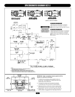
PRIMARY & RELAY VOLTAGE SAME AS LINE VOLTAGE. 3) THREE PHASE UNITS MAY BE EQUIPPED WITH AN INTERNAL PILOT DUTY THERMAL OVERLOAD DEVICE, OR AN EXTERNAL LINE MONITORING DEVICE. OPEN LIMIT SW. DEPRESS PLATE CLOSE LIMIT SW. AUXILIARY OPEN LIMIT SW. ELECTRICAL BOX END VIEW LIMIT NUT SAFETY LIMIT SW - LiftMaster DJ | DJ Locksensor Mechanical Manual - Page 3
PRIMARY & RELAY VOLTAGE SAME AS LINE VOLTAGE. 3) THREE PHASE UNITS MAY BE EQUIPPED WITH AN INTERNAL PILOT DUTY THERMAL OVERLOAD DEVICE, OR AN EXTERNAL LINE MONITORING DEVICE. OPEN LIMIT SW. DEPRESS PLATE CLOSE LIMIT SW. AUXILIARY OPEN LIMIT SW. ELECTRICAL BOX END VIEW LIMIT NUT SAFETY LIMIT SW - LiftMaster DJ | DJ Locksensor Mechanical Manual - Page 4
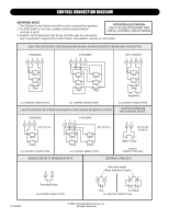
Station provided must be connected for operation. 2. If a STOP button is not used, a jumper must be placed between terminals 3 and 4. ATTENTION ELECTRICIAN: USE 16 GAUGE OR HEAVIER WIRE FOR ALL CONTROL CIRCUIT WIRING. 3. Auxiliary control equipment may be any normally open two wire device such as
-
 1
1 -
 2
2 -
 3
3 -
 4
4
 |
 |
APPLICATION REQUIREMENTS
This wiring modification is available to models DJ and DH/J
Standard-Duty operators with 24Vac control circuits and “D1”
type wiring.
NOTE:
If C2 or B2 wiring is desired refer to conversion
instructions on pages 2 and 3.
FUNCTIONS
This modification stops the operator when extra tension is
sensed on the door from the mechanical door lock, obstruction
or extensive binding.
OPERATION
When the operator senses extra tension when closing, the Lock
Sensor will stop the operator. Press close button and run until
the operator shuts off (to unlock door when load removed).
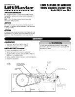
LOCK SENSOR (D1 WIRING)
WIRING DIAGRAM & INSTRUCTIONS
Model: DH, DJ and DH/J
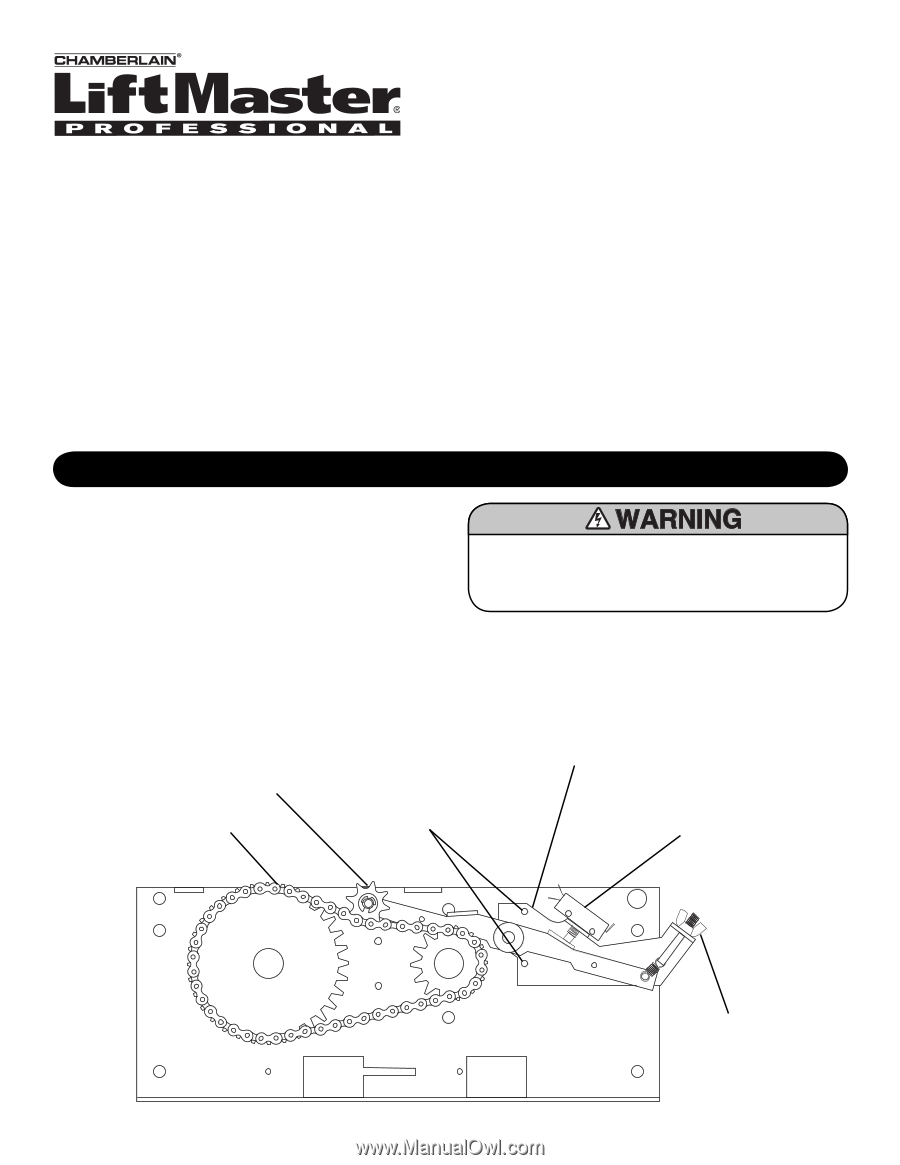
ADJUSTMENT
FINE ADJUSTMENT
•
To increase opening force, tighten wing nut.
•
To decrease opening force, loosen wing nut.
COURSE ADJUSTMENT (if required)
1. Release spring pressure on pivot arm.
2. Loosen but do not remove mounting screws (2).
3.
Fully tension final reduction chain and rotate Lock Sensor
until switch is in activation mode.
4.
Tighten mounting screws (2) to secure Lock Sensor position.
5. Repeat fine adjustments.
Lock Sensor
Assembly
To adjust opening force
tighten or loosen
wing
nut accordingly
Chain Idler Sprocket
must engage top side
of reduction chain
Final Reduction
Chain
Lock Sensor Switch
(held to normally closed)
Mounting
Screws
To avoid SERIOUS PERSONAL INJURY or DEATH from
electrocution, disconnect electric power to operator BEFORE
adjusting Lock Sensor.
FIGURE 1