LiftMaster EL25 EL25 Installation Ver. 3.0 Manual - Page 8
Wire Connections to the Unit
 |
View all LiftMaster EL25 manuals
Add to My Manuals
Save this manual to your list of manuals |
Page 8 highlights
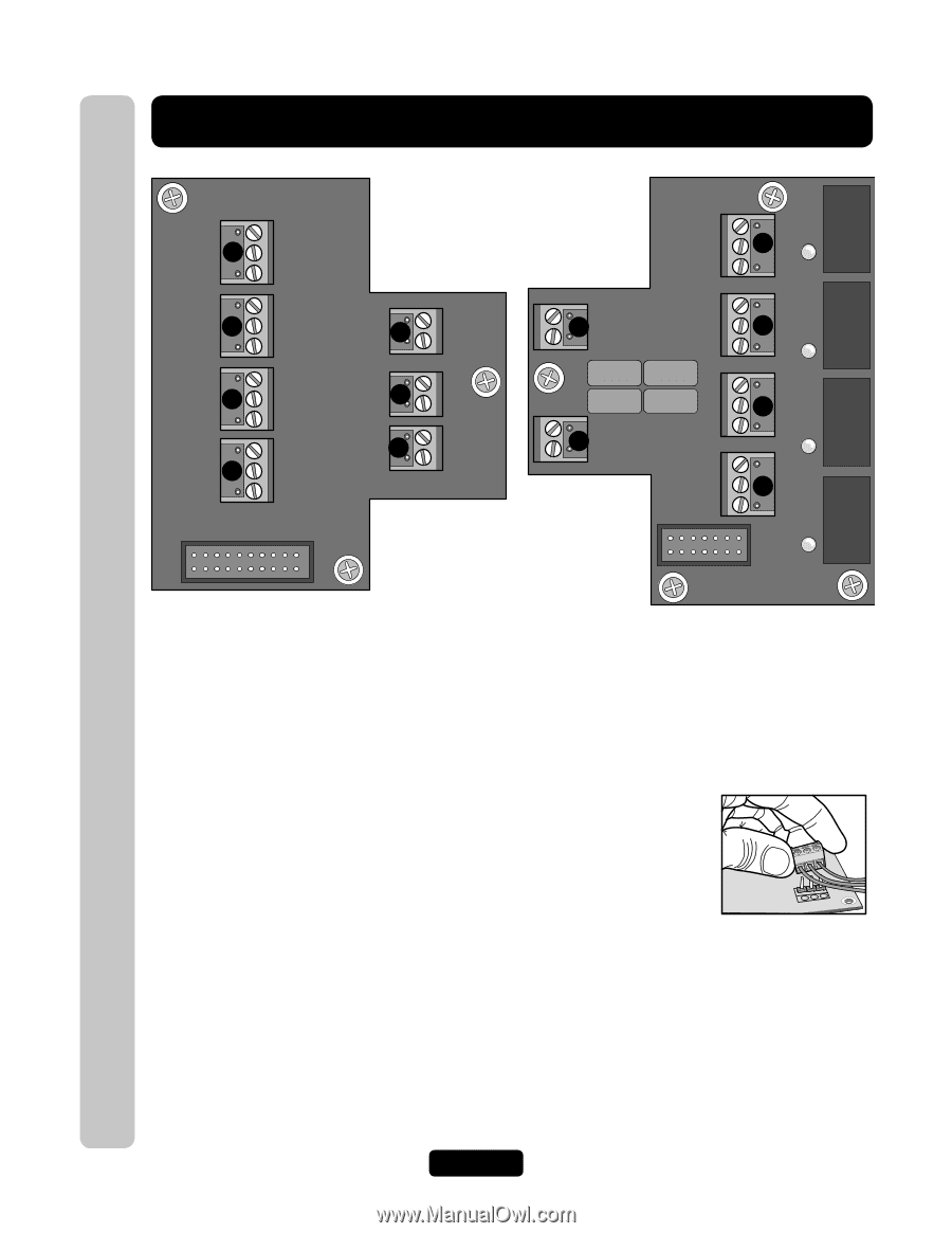
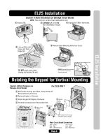
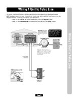
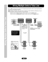
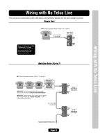
Wire Connections to the Unit Wire Connections to the Unit IO Output Board EXIT REQ 4 4 COM J7 DOOR STAT 4 EXIT REQ 3 3 COM J6 DOOR STAT 3 EXIT REQ 2 2 COM J5 DOOR STAT 4 EXIT REQ 1 1 COM J4 DOOR STAT 1 POSTAL 5 J3 AUTO 6 J2 J1 7 POWER 12VAC/DC IO Input Board RES 8 J6 TELCO 9 J8 20-Pin to Main Board NO J5 10 LED 4 NC C RELAY 4 NO J4 11 NC LED 3 C RELAY 3 NO J3 12 NC C LED 2 NO RELAY 2 13 NC J1 C LED 1 RELAY 1 14-Pin to Main Board Input Board Connections 1. Door 1 Exit Request and Door Status 2. Door 2 Exit Request and Door Status 3. Door 3 Exit Request and Door Status 4. Door 4 Exit Request and Door Status 5. Postal Lock Input 6. AutoCall Input 7. Power 12 VAC Input Output Board Connections 8. Resident Tip/Ring 9. Telco Tip/Ring 10. Relay 4, NO, NC, COM 11. Relay 3, NO, NC, COM 12. Relay 2, NO, NC, COM 13. Relay 1, NO, NC, COM NOTE: All relays are factory set to "Strike" and "10 sec." DO NOT overload the removable terminal block connectors. One wire per hole. Page 6
-
 1
1 -
2
-
 3
3 -
 4
4 -
 5
5 -
 6
6 -
 7
7 -
 8
8 -
 9
9 -
 10
10 -
 11
11 -
 12
12 -
 13
13 -
14
-
15
-
16
-
17
-
18
-
19
-
20
-
21
-
22
-
23
-
24
-
25
-
26
-
27
-
28
-
29
-
30
-
31
-
32
 |
 |