LiftMaster EL25 EL25 Installation Ver. 3.0 Manual - Page 9
Wire Specs and Run Distances
 |
View all LiftMaster EL25 manuals
Add to My Manuals
Save this manual to your list of manuals |
Page 9 highlights
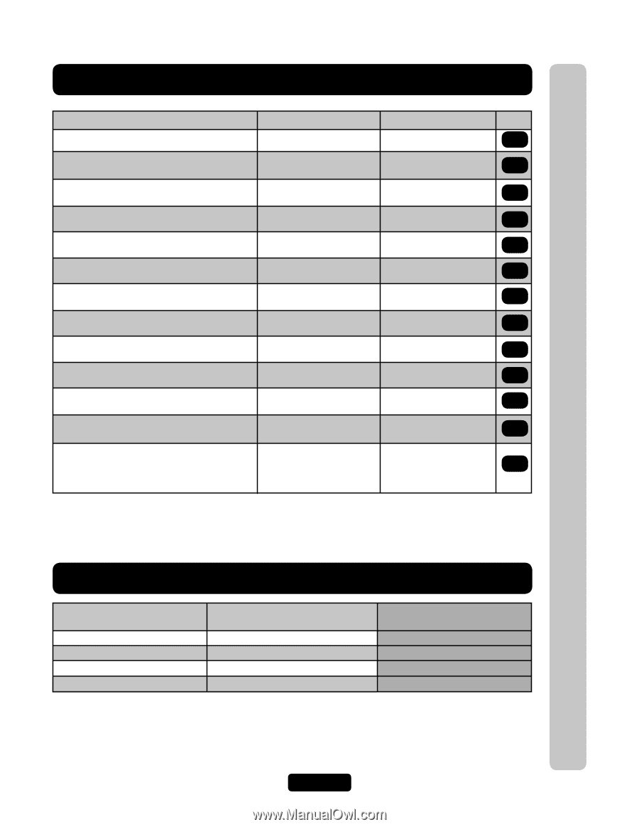
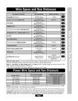
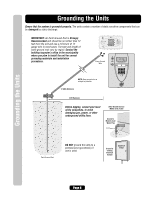
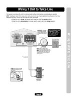
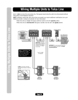
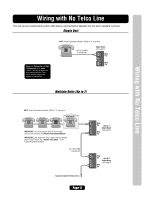
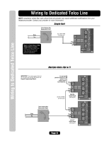
Wire Specs and Run Distances Wire Specs and Run Distances Use this chart to pull wires in preparation of your installation: Description of Wire Run Wire Specification Maximum Distance Page Grounding the Chassis 12 AWG Copper 12 feet 8 Residence and Telco Phone Lines Door Strike Magnetic Lock Dry Contact Closure (Most Gate Operators) Exit Request (REX) / Auxiliary Open Devices AutoCall Door Status Sensor Barium Ferrite and Wiegand Readers Proximity Readers Radio Frequency Module (RF) Postal Lock 2 Twisted Pairs 18-24 AWG Shielded 2-Conductor 18-22 AWG Shielded 2-Conductor 18-22 AWG Shielded 2-Conductor 18-24 AWG Shielded 2-Conductor 18-24 AWG Shielded 2-Conductor 18-24 AWG Shielded 2-Conductor 18-24 AWG Shielded 5-Conductor 18-24 AWG Shielded 5-Conductor 22 AWG Shielded RG-6 Coaxial 75 ohm 2-Conductor 18-24 AWG Shielded 5000 feet* 9-14 15 15 16 16 17 17 500 feet 18 500 feet 18 100 feet 18 19 CCTV Camera (Optional) Single Conductor RG-59u Coaxial 1000 feet (Monitor with a .25 volt 19 p-p composite signal sensitivity) NOTE: Use metal conduit - run wires in metal conduit instead of PVC pipe. Wires run in PVC conduit may experience interference. Metal conduits also add extra protection against lightning strikes. Never run Telco Wires and High Voltage wires in the same conduit. The high voltage may interfere with the Telco Wires, possibly causing the system to malfunction. * Total distance from Telco to residence regardless of number of units in chain. Power Wire Specs and Run Distances Distance at 65° C 12Vac Power (Included) 2-Conductor Shielded 12Vdc Power (Not Provided) 2-Conductor Shielded Under 50 Feet 24 AWG MIN 24 AWG MIN 50 - 100 Feet 20 AWG MIN 20 AWG MIN 100 - 300 Feet 16 AWG MIN 16 AWG MIN 300 - 500 Feet 14 AWG MIN 14 AWG MIN Always provide power from a dedicated source. Plug provided transformer into an outlet wired to its own 10 AMP minimum circuit breaker. This will prevent two problems: • Other equipment cannot introduce spikes, noise, surges or dips into the power circuit that will affect the system. • The system's operation will not be affected if any other equipment develops a short circuit across the power line. CAUTION: Not responsible for conflicts between the information listed in the above table and the requirements of your local building codes. The information is for suggested use only. Check your local codes before installation. Page 7
-
 1
1 -
2
-
3
-
 4
4 -
 5
5 -
 6
6 -
 7
7 -
 8
8 -
 9
9 -
 10
10 -
 11
11 -
 12
12 -
 13
13 -
 14
14 -
15
-
16
-
17
-
18
-
19
-
20
-
21
-
22
-
23
-
24
-
25
-
26
-
27
-
28
-
29
-
30
-
31
-
32
 |
 |