LiftMaster GH GH LOGIC 3 Manual
LiftMaster GH Manual
 |
View all LiftMaster GH manuals
Add to My Manuals
Save this manual to your list of manuals |
LiftMaster GH manual content summary:
- LiftMaster GH | GH LOGIC 3 Manual - Page 1
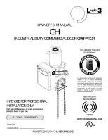
L 3 ogic OWNER'S MANUAL GH INDUSTRIAL DUTY COMMERCIAL DOOR OPERATOR This Operator Features the Enhanced INTENAN MA E M E C AL E PATENT PENDING R T T SYS The Maintenance Alert System™ allows the installer to set an internal Maintenance Cycle Counter. The Logic 3 operator incorporates a self- - LiftMaster GH | GH LOGIC 3 Manual - Page 2
Wiring Connections 10 CONTROL STATION WIRING & INSTALLATION Control Wiring Connections 11 Mounting Instructions 11 External Radio Wiring Connections 11 DIAGRAMS Standard Power & Control Connection Diagrams 12 1 Phase Wiring Diagram 13 3 Phase Wiring Diagram 14 Logic Board 15 PROGRAMMING - LiftMaster GH | GH LOGIC 3 Manual - Page 3
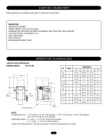
HAND CHAIN DOOR SPROCKET DOOR/OPERATOR DRIVE CHAIN OPERATOR DIMENSIONS WEIGHTS AND DIMENSIONS HANGING WEIGHT: 80-110 LBS. A Y See Note #2 14.00" B See Note #1 X Hand Chain Wheel HP PHASE 1/2 1 A 11-1/2 3/4 1 12-1/2 1 1 12-3/4 D 1-1/2 1 12-3/4 1/2 3 11 3/4 3 11 Y 1 3 12 - LiftMaster GH | GH LOGIC 3 Manual - Page 4
optional wiring types and operating modes. LIMIT ADJUST Linear driven, fully adjustable screw type cams MECHANICAL DRIVE REDUCTION 45:1 for 1/2, 3/4, and 1 HP 44:1 for 1-1/2, 2 42:1 for 3 HP OUTPUT SHAFT SPEED 38.3 for 1/2, 3/4, and 1 HP 39.2 for 1-1/2 and 2 HP 41.1 for 3 HP DOOR SPEED 4 - 10 - LiftMaster GH | GH LOGIC 3 Manual - Page 5
move or adjust doors, door springs, cables, pulleys, brackets or their hardware, ALL of which are under EXTREME tension and can cause SERIOUS personal INJURY. AVERTISSEMENT • Disable ALL locks and remove ALL ropes connected to door BEFORE installing and operating door operator to avoid entanglement - LiftMaster GH | GH LOGIC 3 Manual - Page 6
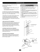
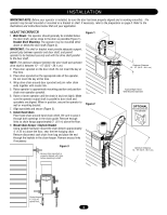
is parallel to door shaft and sprockets are aligned. When in position, secure the operator to wall or mounting bracket. 7. Align sprockets and secure (Figure 3). 8. Install Hand Chain Place hand chain around hand chain wheel. Be sure to pass it through both openings in the chain guide. Remove enough - LiftMaster GH | GH LOGIC 3 Manual - Page 7
controls when the hoist is used. WARNING To prevent possible SERIOUS INJURY from a moving chain, CAUTION ENGAGE interlock BEFORE manually operating your door. To operate the hoist: 1. Pull the disconnect chain (small chain) to engage the interlock to disable the controls. The disconnect chain - LiftMaster GH | GH LOGIC 3 Manual - Page 8
the door according to the instructions provided with the edge. The sensing edge may be electrically connected by either coiled cord or take-up reel. Important Notes: a. Proceed with limit switch adjustments described below before making any sensing edge wiring connections to operator. b. Electrician - LiftMaster GH | GH LOGIC 3 Manual - Page 9
there is very little tension on the clutch spring. 3. Tighten clutch nut gradually until there is just enough tension to permit the operator to move the door smoothly but to allow the clutch to slip if the door is obstructed. When the clutch is properly adjusted, it should generally be possible to - LiftMaster GH | GH LOGIC 3 Manual - Page 10
accordance with local electrical codes. The operator should be on a separate fused line of adequate capacity. • ALL electrical connections MUST be made by a qualified individual. • DO NOT install ANY wiring or attempt to run the operator without consulting the wiring diagram. We recommend that you - LiftMaster GH | GH LOGIC 3 Manual - Page 11
: The motor direction change is not available on the DJ and DH models. EXTERNAL RADIO WIRING CONNECTIONS On all models a radio terminal bracket marked R1 R2 R3 is located on the outside of the electrical enclosure. In B2 mode the operator will then open a fully closed door, close a fully open door - LiftMaster GH | GH LOGIC 3 Manual - Page 12
CONNECTION DIAGRAMS Radio Control (24V DC only) CPS-L & CPS-LN4 R3 R2 R1 Sensing Edge Timer Defeat Switch Maintenance Alert LED (RD) (WH) Open Close Stop Open/Close Single Button OPEN CLOSE STOP 3-Button Station Remove Jumper To Install External Interlock Single Phase Power Wiring Line - LiftMaster GH | GH LOGIC 3 Manual - Page 13
LOGIC (VER. 3.0) 1 PHASE WIRING DIAGRAM 115V MOTOR CONNECTION 230V MOTOR CONNECTION NOTE: Gray (GY) and purple (PU) motor wires are reversed for H and HJ right hand models and all GH and J models. CPS-L & CPS-LN4 Sensing Edge Hoist Interlock When Present TMR DEF SWITCH (YE) (BL) Maintenance - LiftMaster GH | GH LOGIC 3 Manual - Page 14
) and purple (PU) motor wires are reversed for H and HJ right hand models and all GH and J models. Sensing Edge CPS-L & CPS-LN4 Hoist Interlock When Present TMR DEF SWITCH (YE) (BL) Maintenance Alert LED (RD) (WH) Open Close Stop OPEN CLOSE STOP 3-Button Station Open/Close Single Button - LiftMaster GH | GH LOGIC 3 Manual - Page 15
D14 P1 D34 MAS 10 EYES 9 EDGE 8 OPEN 7 CLOSE 6 STOP 5 CMN 4 3 2 SBC 1 F1 C54 C71 C78 ® Motor Direction Jumper Single Phase and Three Phase Jumper Maintenance Alert System Button for Programming Open Button Close Button Stop Button Control Wiring Terminal Block Wiring Type Selector Dial - LiftMaster GH | GH LOGIC 3 Manual - Page 16
have door control at the electrical box. Either the stop control or a jumper must be wired between terminals 4 and 5 for the on board push buttons to function. NOTE: Refer to logic board illustration on page 15 for all component locations. Before programming the logic board, set the operators open - LiftMaster GH | GH LOGIC 3 Manual - Page 17
Requires self monitoring photo eyes to operate.) FSTS Momentary button contact for open, close and stop programming. Radio controls allowing open, close and stop. User set mid stop. User set Timer To Close. The single button station opens the door to the full open limit bypassing the mid stop and - LiftMaster GH | GH LOGIC 3 Manual - Page 18
Canada (IC) rules, adjustment or modifications of this receiver and/or transmitter are prohibited, except for changing the code setting or replacing the battery. THERE ARE NO OTHER USER SERVICEABLE PARTS. Tested to Comply with FCC Standards FOR HOME OR OFFICE USE. Operation is subject to the - LiftMaster GH | GH LOGIC 3 Manual - Page 19
be programmed to operate as a 3-button wireless control station: the large button will open the door, the middle button will close the door, and the third button will stop the door's movement. You may set up this feature as follows: 1. To enter programming press the RADIO button on the logic board - LiftMaster GH | GH LOGIC 3 Manual - Page 20
pause, an operator error occurred. Turn to page 28 to diagnose problem. Example: A door is installed with 30,000 cycle springs and has an annual service contract. To set the MAS, turn selector dial to PROGRAM, press MAS button, press the STOP button to clear the memory and then press the OPEN button - LiftMaster GH | GH LOGIC 3 Manual - Page 21
or FSTS. TO PROGRAM MANUALLY (Method 1): SELECTOR DIAL 1. Close the door. 2. Turn the selector dial to PROGRAM. 3. Press the TIMER button on the logic board. 4. Press the STOP button to clear the timer. AVERTISSEMENT 5. Press the OPEN button for every 5 seconds the operator should wait before - LiftMaster GH | GH LOGIC 3 Manual - Page 22
close only one time for safety purposes. SELECTOR DIAL Operation will vary depending on wiring type CAR DEALER MODE Feature: The car dealer mode uses the SBC (Single Button Control input) to bring the door from a closed position to the programmed Open Mid-Stop position and keep it at that location - LiftMaster GH | GH LOGIC 3 Manual - Page 23
on models GH and GT.) NOTE: This feature is automatically learned and does not require programming. LOSE OPEN RPM Sensor Logic Board MAXIMUM RUN TIMER (MRT) Feature: The operator can learn the time it takes to open or close the door plus an additional 10 seconds. Benefit: If the operator does - LiftMaster GH | GH LOGIC 3 Manual - Page 24
Less than or equal Activates when the door reaches the open to 10 seconds limit or mid stop The red lamp holder receives power when the door opens and remains activated if the door is stopped manually before reaching the mid stop or the open limit RESETTING FACTORY DEFAULTS - CLEARING MEMORY To - LiftMaster GH | GH LOGIC 3 Manual - Page 25
desired wiring type. NOTE: If the operator has not reached 5,000 cycles or 3 months, there will be no indications. 25 HOW TO ORDER REPAIR PARTS OUR LARGE SERVICE ORGANIZATION SPANS AMERICA Installation and service information are available. Call our TOLL FREE number: 1-800-528-2806 www.liftmaster - LiftMaster GH | GH LOGIC 3 Manual - Page 26
logic board has several LEDs to assist in the installation and troubleshooting of the operator. The following chart should assist in verifying the operator is functioning properly. Turn the selector dial to DIAGNOSTIC to keep the door from moving while troubleshooting. LED Power Stop Open COLOR - LiftMaster GH | GH LOGIC 3 Manual - Page 27
TROUBLESHOOTING GUIDE FAULT THE OPERATOR WILL NOT RESPOND TO ANY COMMANDS POSSIBLE CAUSE FIX a) No power supply b) Operator control station is wired wrong c) Interlock switch is activated d) Dial still in programming or diagnostic mode e) Motor is malfunctioning f) Motor thermal overload tripped - LiftMaster GH | GH LOGIC 3 Manual - Page 28
on the MAS LED. ERROR CODE DESCRIPTION EFFECT DISPLAY CORRECTION E1 MAS triggered (cycles or None normal operation. months). 1 blink Reset MAS. E2 No RPM input during The door only responds to 2 blinks Clutch is slipping, adjust clutch, or opening or closing. constant pressure - LiftMaster GH | GH LOGIC 3 Manual - Page 29
NOTE: Radio receiver is compatible with 315 MHz remotes. ERROR CODE SYMPTOM DISPLAY POSSIBLE PROBLEM CORRECTION R1 No response from Quick Flash Unlearned remote - A - OR - the radio being learned is not compatible with the operator. R4 The remote 2 Blinks No free records - A user enters - LiftMaster GH | GH LOGIC 3 Manual - Page 30
ELECTRICAL BOX 6 5 9 10 4 7 2 3 K2 (K72-12515-1) 11 8 1 K1 (K72-10047) (K72-10047-1) 30 - LiftMaster GH | GH LOGIC 3 Manual - Page 31
and locknuts. * To order a complete electrical box kit, add a K- prefix to the model number of your operator. For example: GH5011L3 (Operator) = K-GH5011L3 (Electrical box kit) ITEM 1 2 3 4 5 6 7 8 9 10 11 INDIVIDUAL PARTS PART # DESCRIPTION 13-10024 Limit nut 23-10041 Limit switch K75-32268 - LiftMaster GH | GH LOGIC 3 Manual - Page 32
MODEL GH K5 (K75-12829) (K75-12830) (K75-12831) (K75-12832) (K75-12833) 16 4 3 5 K2 (K75-10177) 2 1 K1 (K75-12584) (K75-12585) (K75-12586) K4 (K75-30737) 20 19 18 7 6 17 13 K3 (K72-12789) 9 13 14 12 8 11 10 15 32 - LiftMaster GH | GH LOGIC 3 Manual - Page 33
24 tooth (3 HP) 10 10-10882 Hand chain guide 11 12-10883 Nyliner bearing 12 11-11105 Hand chain shaft 13 12-10029 Bearing, 3/4" I.D. 14 18-11008 Compression spring 15 75-10884 Chain wheel assembly 16 K20-1050C-2LP Motor - models GH5011L3, GH5021L3 K20-3050C-4P Motor - models GH5023L3 - LiftMaster GH | GH LOGIC 3 Manual - Page 34
OPERATOR NOTES 34 - LiftMaster GH | GH LOGIC 3 Manual - Page 35
OPERATOR NOTES 35 - LiftMaster GH | GH LOGIC 3 Manual - Page 36
proper installation and operation with the Commercial Door Operator. 3 BUTTON STATION OR 3 POSITION KEYSWITCH WITH SPRING RETURN TO CENTER AND STOP BUTTON STANDARD 10 7 6 4 5 2 OR MORE 10 7 6 4 5 KEY LOCKOUT 10 7 6 4 5 (RED) (RED) (RED) Open Open Maintenance Open Open Maintenance Alert
-
 1
1 -
 2
2 -
 3
3 -
 4
4 -
 5
5 -
 6
6 -
 7
7 -
8
-
9
-
10
-
11
-
12
-
13
-
14
-
15
-
16
-
17
-
18
-
19
-
20
-
21
-
22
-
23
-
24
-
25
-
26
-
27
-
28
-
29
-
30
-
31
-
32
-
33
-
34
-
35
-
36
 |
 |

This Operator Features
the Enhanced
Radio Receiver
Built on Board
O W N E R ’ S
M A N U A L
GH
INDUSTRIAL DUTY COMMERCIAL DOOR OPERATOR
ogic
L
3
NOT FOR RESIDENTIAL USE
A
L
E
R
T
S
Y
S
T
E
M
M
A
I
N
T
E
N
A
N
C
E
PATENT PENDING
The Maintenance Alert System™ allows the
installer to set an internal Maintenance
Cycle Counter. The Logic 3 operator
incorporates a self-diagnostic feature built
into the (MAS) Maintenance Alert System
LED. An LED on the 3-button station will
signal when the set number of cycles/
months is reached or when the operator
requires immediate service.
Serial # Box
Installation Date
2
YEAR
WARRANTY
315MHz
Visit www.LiftMaster.com to locate a professional
installing dealer in your area.
INTENDED FOR PROFESSIONAL
INSTALLATION ONLY
A SAFETY DEVICE IS HIGHLY RECOMMENDED