LiftMaster GH GT- Logic 4 Installation Manual - Page 18
Wiring - motor
 |
View all LiftMaster GH manuals
Add to My Manuals
Save this manual to your list of manuals |
Page 18 highlights
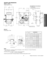
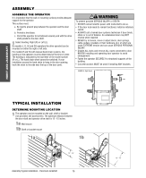
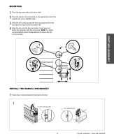
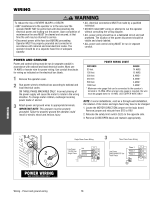
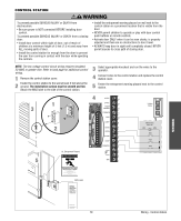
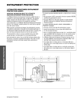
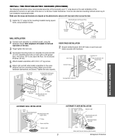
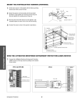
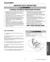
WIRING WARNING To reduce the risk of SEVERE INJURY or DEATH: • ANY maintenance to the operator or in the area near the operator MUST NOT be performed until disconnecting the electrical power and locking-out the power. Upon completion of maintenance the area MUST be cleared and secured, at that time the unit may be returned to service. • Disconnect power at the fuse box BEFORE proceeding. Operator MUST be properly grounded and connected in accordance with national and local electrical codes. The operator should be on a separate fused line of adequate capacity. • ALL electrical connections MUST be made by a qualified individual. • DO NOT install ANY wiring or attempt to run the operator without consulting the wiring diagram. • ALL power wiring should be on a dedicated circuit and well protected. The location of the power disconnect should be visible and clearly labeled. • ALL power and control wiring MUST be run in separate conduit. POWER AND GROUND Power and control wiring must be run in separate conduit in accordance with national and local electrical codes. Must use 14 AWG or heavier wire for power wiring. Use conduit knockouts for wiring as indicated on the electrical box labels. 1 Remove the operator cover. 2 Run power wires to electrical box according to national and local electrical codes. ON THREE PHASE MACHINES ONLY: Incorrect phasing of the power supply will cause the motor to rotate in the wrong direction. To change motor rotation, exchange incoming power leads L1 and L2. 3 Attach power and ground wires to appropriate terminals. IMPORTANT NOTE: This operator must be properly grounded. Failure to properly ground the operator could result in electric shock and serious injury. POWER WIRING CHART DISTANCE GAUGE 50 feet 14 AWG 100 feet 12 AWG 200 feet 8 AWG* 350 feet 6 AWG* 500 feet 4 AWG* 1000 feet 2 AWG* * Maximum wire gauge that can be connected to the operator's terminal is 12 AWG. When a larger wire gauge is required, the wire must be gauged down to 12 AWG. USE COPPER WIRE ONLY. NOTE: In some installations, such as a through-wall-installation, the rotation of the motor and logic board may have to be changed. 1. Locate the MOTOR DIRECTION jumper on the logic board. Remove jumper and relocate from STD to REV. 2. Relocate the safety limit switch (SLS) to the opposite side. 3. Remove CLOSE/OPEN decal and reattach appropriately. 1 Single Phase Power Wiring 3 Three Phase Power Wiring Line Power Hot 2 115/230 Vac Single Phase Neutral Ground Line Power 208/230/460/575 Vac Three Phase Phase 1 Phase 2 Phase 3 WIRING Wiring - Power and ground wiring 18
-
 1
1 -
2
-
3
-
4
-
5
-
6
-
7
-
8
-
9
-
10
-
11
-
12
-
 13
13 -
 14
14 -
 15
15 -
 16
16 -
 17
17 -
 18
18 -
 19
19 -
 20
20 -
 21
21 -
 22
22 -
 23
23 -
24
-
25
-
26
-
27
-
28
-
29
-
30
-
31
-
32
-
33
-
34
-
35
-
36
-
37
-
38
-
39
-
40
-
41
-
42
-
43
-
44
 |
 |