LiftMaster GH GT- Logic 4 Installation Manual - Page 21
Install The Photoelectric Sensors Provided
 |
View all LiftMaster GH manuals
Add to My Manuals
Save this manual to your list of manuals |
Page 21 highlights
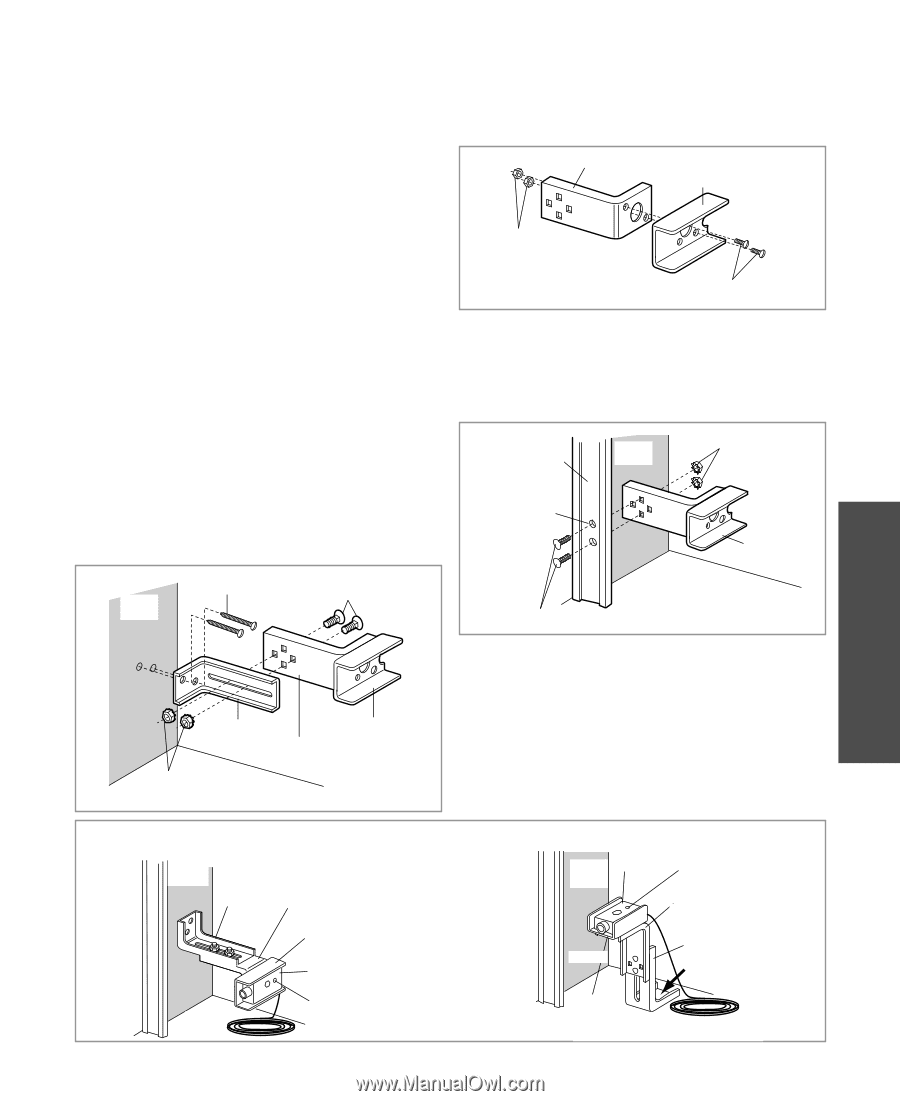
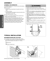
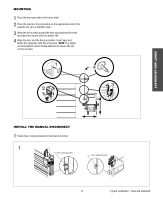
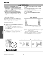
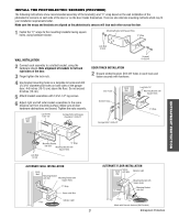
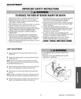
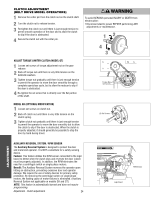
INSTALL THE PHOTOELECTRIC SENSORS (PROVIDED) The following instructions show recommended assembly of the bracket(s) and "C" wrap based on the wall installation of the photoelectric sensors on each side of the door or on the door tracks themselves. There are also alternate mounting methods which may fit your installation requirements better. Make sure the wraps and brackets are aligned so the photoelectric sensors will face each other across the door. 1 Fasten the "C" wraps to the mounting brackets having square holes, using hardware shown. Mounting Bracket with Square Holes "C" Wrap Lock Nuts #10-32 WALL INSTALLATION 2 Connect each assembly to a slotted bracket, using the hardware shown. Note alignment of brackets for left and right sides of the door. 3 Finger tighten the lock nuts. 4 Use bracket mounting holes as a template to locate and drill (2) 3/16" diameter pilot holes on both sides of the garage door, 4-6 inches (10-15 cm) above the floor. Do not exceed 6 inches (15 cm). 5 Attach bracket assemblies with 1/4"x1-1/2" lag screws. 6 Adjust right and left side bracket assemblies to the same distance out from mounting surface. Make sure all door hardware obstructions are cleared. Tighten the nuts securely. Inside Wall Lag Screws 1/4x1-1/2" Carriage Bolts (with square shoulders) 1/4-20x12" Screws# 10-32x3/8" DOOR TRACK INSTALLATION 2 Discard slotted bracket. Drill 3/8" holes in each track and fasten securely with hardware. Door Track Drill 3/8" Holes Inside Wall Lock Nuts 1/4" Mounting Bracket with Square Holes "C" Wrap Carriage Bolts 1/4-20x1/2" ENTRAPMENT PROTECTION Mounting Bracket "C" Wrap with Slot Mounting Bracket with Square Holes Lock Nuts 1/4"-20 ALTERNATE WALL INSTALLATION Inside Wall Mounting Bracket with Slot Mounting Bracket with Square Holes "C" Wrap Sensor with Wire - Floor - Indicator Light ALTERNATE FLOOR INSTALLATION Sensor Inside with Wire Wall Indicator Light "C" Wrap Mounting Bracket with Square Holes Mounting Bracket with Slot - Floor - Attach with Concrete Anchors (Not Provided) 21 Entrapment Protection
-
 1
1 -
2
-
3
-
4
-
5
-
6
-
7
-
8
-
9
-
10
-
11
-
12
-
13
-
14
-
15
-
 16
16 -
 17
17 -
 18
18 -
 19
19 -
 20
20 -
 21
21 -
 22
22 -
 23
23 -
 24
24 -
 25
25 -
 26
26 -
27
-
28
-
29
-
30
-
31
-
32
-
33
-
34
-
35
-
36
-
37
-
38
-
39
-
40
-
41
-
42
-
43
-
44
 |
 |