LiftMaster GH GT- Logic 4 Installation Manual - Page 25
Testing - g door code
 |
View all LiftMaster GH manuals
Add to My Manuals
Save this manual to your list of manuals |
Page 25 highlights
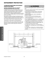
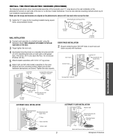
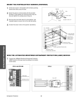
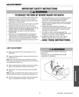
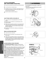
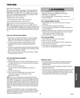
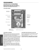
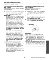
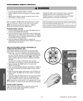
TESWTIANRGNING WARNING CAUTION Apply power to the operator. When power is applied to the operator, the following LED's will illuminate: STOP, CLOSE, OPEN, LMEP, 24Vac, RADIO, DATA, TIMER ENABLE, OLS MID, SLS, CLS, and MAS. Once the power up process is completed (approximately 2-3 seconds) only the appropriate LED's will continue to be lit: • Between limits: 24Vac and STOP • Fully closed position: 24Vac, STOP, CLS and SLS • Fully opened position: 24Vac, STOP and OLS Additional LED's will light when device(s) are activated. NOTE: When the power up process is over, the MAS LED will blink a code indicating the version of firmware. If the selector dial is in the DIAG, OPTN, or PROG position, the MAS will not provide AVERTISSEMENT this code. After the code has been provided the MAS LED will go out. ALIAGNTTHTEEPHNOTTOEILOECTNRIC SENSORS 1. After power is connected to the operator, the green indicator lights in both the sending and receiving sensors will glow steadily if wiring connections and alignment are correct. 2. If the green indicator lights are flashing rapidly (and the invisible light beam path is not obstructed), alignment is required: • Loosen the receiving sensor wing nut to allow slight rotation of the sensor. Adjust sensor vertically and/or horizontally until the green indicator light glows steadily. • When the indicator lights are glowing in both sensors, tighten the receiving sensor wing nut. WARNING To avoid SERIOUS personal INJURY or DEATH: • Disconnect electric power BEFORE performing ANY adjustments or maintenance. • ALL maintenance MUST be performed by a trained door systems technician. TEST 3-BUTTON CONTROL STATION 1. Press OPEN button. (The door should move in the open direction.) 2. Press STOP button. (The door should stop.) 3. Press and hold the CLOSE button. (The door should move in AVERTISSEMENT the close direction.) 4. Release CLOSE button. Door should stop if in C2 or D1 mode. Door will reverse to full open position in E2 mode. The door should continue closing in all other modes. 5. Press STOP buAttonV. (ETheRdoTorIsShoSuldEstoMp.)ENT TEST LIMIT ADJUSTMENT 1. Press OPEN button. (The door should open.) 2. Allow the door to fully open. 3. Press and hold the CLOSE button. (The door should close.) 4. Allow the door to fully close. 5. If the limits are not set properly, remove power and adjust limits (refer to Limit Adjustment section). TESTING TEST THE PHOTOELECTRIC SENSORS 1. Open the door. ADVERTENCIA 2. Place an obstruction in the path of the photoelectric sensors. The LMEP LED will blink on the logic board and the receiving eye LED will turn off. 3P. PRresEs aCndAhoUld tChe ICÓLOSNE button. The door should not close if photoelectric sensors are installed. 4. Remove the obstruction. 5. Press and hold the CLOSE button. Door should close. If door did not reverse from obstruction, check photoelectric sensors. NOTE: The Logic 4 control board will automatically learn the photoelectric sensors (LMEP) once they are properly connected. If the LMEP is misaligned or disconnected the LMEP LED on the logic control board will blink on and off. You can close the door by entering the Restricted Close (RC) mode by holding the close button. The operator will begin closing after 5 seconds and will continue to close to the Close Limit or when the close button is released. To unlearn the photoelectric sensors, turn the selector dial to DIAG, push and hold the stop button until the MAS LED flashes. Without the photoelectric sensors connected the only mode of operation will be B2, D1 or E2. IMPORTANT NOTES: ADVERTENCIA • Do not leave power to the operator on unless all safety and entrapment protection devices have been tested and are working properly. ADVERTENCIA • Be sure you have read and understand all safety instructions included in this manual. • Be sure the owner or person(s) responsible for operation of the door have read and understand the safety instructions, know how to electrically operate the door in a safe manner and how to manually disconnect the door from the operator. 25 Testing
-
 1
1 -
2
-
3
-
4
-
5
-
6
-
7
-
8
-
9
-
10
-
11
-
12
-
13
-
14
-
15
-
16
-
17
-
18
-
19
-
 20
20 -
 21
21 -
 22
22 -
 23
23 -
 24
24 -
 25
25 -
 26
26 -
 27
27 -
 28
28 -
 29
29 -
 30
30 -
31
-
32
-
33
-
34
-
35
-
36
-
37
-
38
-
39
-
40
-
41
-
42
-
43
-
44
 |
 |