LiftMaster GH GT- Logic 4 Installation Manual - Page 36
Maintenance - parts manual
 |
View all LiftMaster GH manuals
Add to My Manuals
Save this manual to your list of manuals |
Page 36 highlights
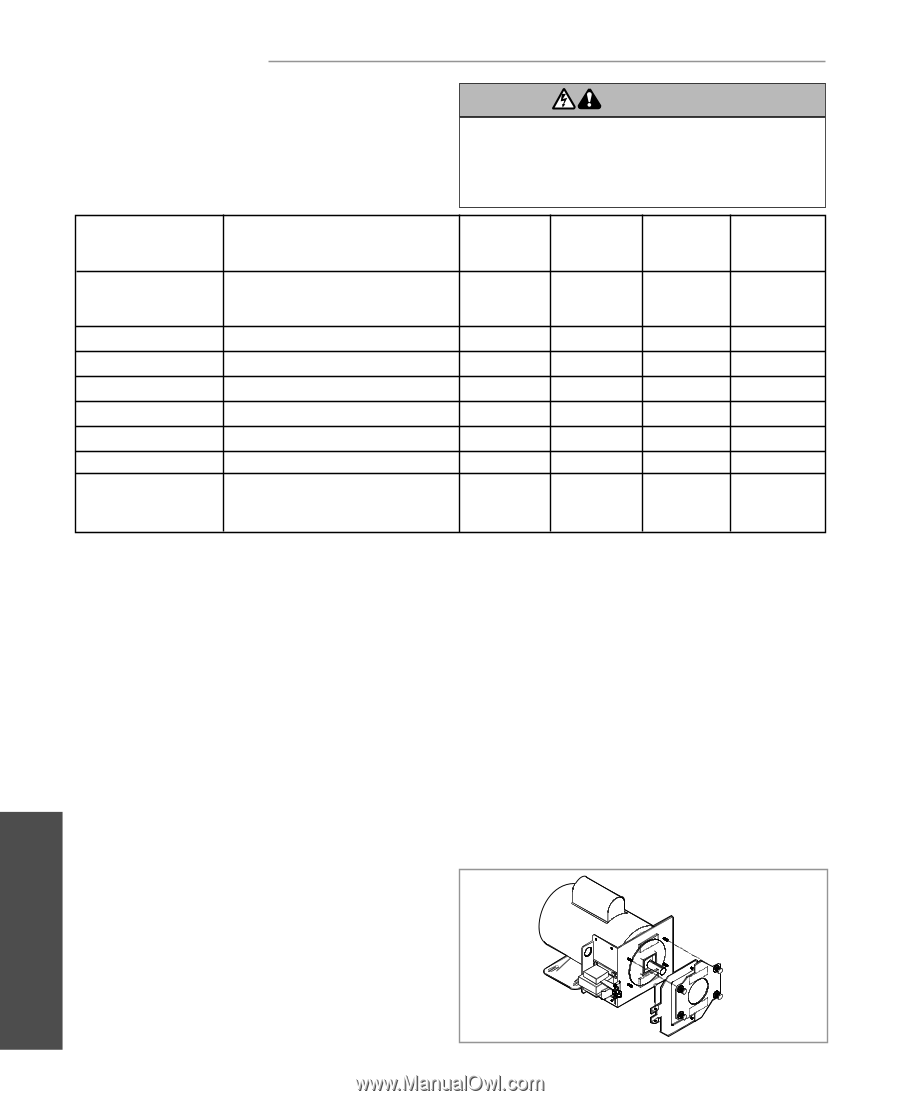
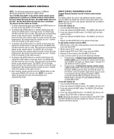
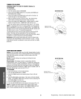
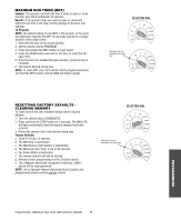
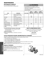
MAIWNTAERNNAINNGCE CAUTION MAINTENANCE SCHEDULE For use with Maintenance Alert System. Check at the intervals listed in the following chart: WARNING WARNING To avoid SERIOUS personal INJURY or DEATH: • Disconnect electric power BEFORE performing ANY adjustments or maintenance. • ALL maintenance MUST be performed by a trained door systems technician. ITEM PROCEDURE Drive Chain Check for excessive slack. Check and adjust as required. ASpVrocEketRs TISSEMENLCuhTbercikcasteet. screw tightness. Clutch Check and adjust as required. BeAlt TTENTION Check condition and tension. Fasteners Check and tighten as required. Manual Disconnect Check and operate. Bearings and Shafts LiftMaster Monitored Entrapment Protection (LMEP) Check for wear and lubricate. Check alignment and functionality. EVERY MONTH EVERY 3 EVERY 6 EVERY 12 MONTHS OR MONTHS OR MONTHS OR 5,000 CYCLES 10,000 CYCLES 20,000 CYCLES AVEz6RTISSEMENT z z AVERTISSzEMENT z z z6 z 6 Use SAE 30 Oil (Never use grease or silicone spray). • Do not lubricate motor. Motor bearings are rated for continuous operation. • Do not lubricate clutch or V-belt. Repeat ALL procedures. z Inspect and service whenever a malfunction is observed or suspected. HOW TO ORDER REPAIR PARTS OUR LARGE SERVICE ORGANIZATION SPANS AMERICA Installation and service information are available. Call our TOLL FREE number: 1-800-528-2806 www.liftmaster.com LIFAEDOVFEORPETREATNOCRIFAEATURE (ODOMETER/CYCLE COUNATEDR)VERTENCIA The operator is equipped with an odometer to show how many months and cycles the operator has performed from the time it as installed. This feature can help determine how long the operator has been in service. PRECAUCIÓN 1. Start with the door in the closed position. ADVERTENCIA 2. Turn the SELECTOR DIAL to DIAG (diagnostic mode). 3. Press and release the MAS button on the logic board. 4. Press and release the MRT button on the logic board. 5. The open and close lights will flash. OPEN for every 5,000 cycles and CLOSE for every 3 months. 6. Return the SELECTOR DIAL to the desired wiring type. NOTE: If the operator has not reached 5,000 cycles or 3 months, there will be no indications. BRAKE (IF PRESENT) A solenoid brake is available as an option for some models. The brake is adjusted at the factory and should not need additional adjustment for the life of the brake assembly. Inspect the brake pad and replace brake assembly when necessary. NOTE: Your operator may look different than the operator shown. MAINTENANCE 36 Maintenance
-
 1
1 -
2
-
3
-
4
-
5
-
6
-
7
-
8
-
9
-
10
-
11
-
12
-
13
-
14
-
15
-
16
-
17
-
18
-
19
-
20
-
21
-
22
-
23
-
24
-
25
-
26
-
27
-
28
-
29
-
30
-
 31
31 -
 32
32 -
 33
33 -
 34
34 -
 35
35 -
 36
36 -
 37
37 -
 38
38 -
 39
39 -
 40
40 -
 41
41 -
42
-
43
-
44
 |
 |