LiftMaster GH GT- Logic 4 Installation Manual - Page 37
Troubleshooting
 |
View all LiftMaster GH manuals
Add to My Manuals
Save this manual to your list of manuals |
Page 37 highlights
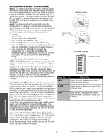
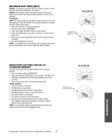
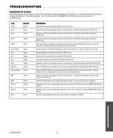
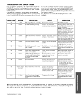
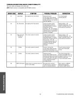
TROUBLESHOOTING DIAGNOSTIC CHART The logic board has several LEDs to assist in the installation and troubleshooting of the operator. The following chart should assist in verifying the operator is functioning properly. Turn the selector dial to DIAGNOSTIC to keep the door from moving while troubleshooting. LED Power Stop Open COLOR Green Green Yellow Close Yellow LMEP Green Timer Defeat OLS CLS SLS Edge Mid Stop Timer Enabled Yellow Yellow Yellow Yellow Yellow Yellow Green SBC Yellow MAS Relay A Yellow Yellow Relay B Yellow DATA Green DEFINITION Indicates that power is being generated for the logic board. Indicates a closed circuit between common and terminal 5. Pressing stop should turn off this LED. Indicates a closed circuit between common and terminal 7. Pressing the open button should turn ON this LED. Indicates a closed circuit between common and terminal 6. Pressing the close button should turn ON this LED. Solid on indicates photoelectric sensors learned. Flashing indicates photoelectric sensors need to be connected or obstructed. Solid off indicates no sensors learned. Solid on indicates a closed circuit between common and terminal 12. Timer-To-Close will not close. Pressing the Open Limit Switch should turn ON this LED. Pressing the Close Limit Switch should turn ON this LED. Pressing the Sensing Limit Switch should turn ON this LED. Indicates a closed circuit between common and terminal 8. Pressing the edge should turn ON this LED. Solid on indicates door is stopped on up or down mid stop. Flashing indicates MID STOP is being set. Solid on indicates TIMER is programmed and will activate from open or mid stop position. Flashing indicates Timer is counting down and door will close after preset time. Indicates a closed circuit between common and terminal 1. Pressing the single button control station should turn ON this LED. Indicates the Maintenance Alert System has been activated or an error code has been triggered. Indicates open or close command has been given to the motor. LED turns on when OPEN/CLOSE button is pressed. Indicates open or close command has been given to the motor. LED turns on when OPEN/CLOSE button is pressed. Indicates communication between the Logic 4 board and optional TLSCARD. TROUBLESHOOTING Troubleshooting 37
-
 1
1 -
2
-
3
-
4
-
5
-
6
-
7
-
8
-
9
-
10
-
11
-
12
-
13
-
14
-
15
-
16
-
17
-
18
-
19
-
20
-
21
-
22
-
23
-
24
-
25
-
26
-
27
-
28
-
29
-
30
-
31
-
 32
32 -
 33
33 -
 34
34 -
 35
35 -
 36
36 -
 37
37 -
 38
38 -
 39
39 -
 40
40 -
 41
41 -
 42
42 -
43
-
44
 |
 |