LiftMaster GH GT- Logic 4 Installation Manual - Page 38
Fault, Possible Cause - series
 |
View all LiftMaster GH manuals
Add to My Manuals
Save this manual to your list of manuals |
Page 38 highlights
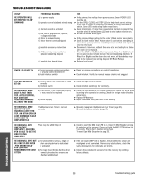
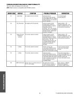
TROUBLESHOOTING GUIDE FAULT THE OPERATOR WILL NOT RESPOND TO ANY COMMANDS POSSIBLE CAUSE FIX a) No power supply b) Operator control station is wired wrong c) Interlock switch is activated d) Dial still in programming, option, or diagnostic mode e) Motor is malfunctioning f) Motor thermal overload tripped g) Possible accessory malfunction h) Off Board relay may need to be replaced see wiring diagram i) Possible logic board failure ➤ Verify primary line voltage from power source. Green POWER LED must be on. ➤ Use the OPEN, CLOSE and STOP LEDs to help check correct wiring. Verify that the board is accepting commands by using the onboard station. Green LED next to stop button must be on. ➤ Check Interlock(s). If more than one external interlock is present they must be wired in series. Green LED next to stop button must be on. ➤ Set dial to desired wiring type. ➤ Verify proper voltage getting to the motor (Check motor name plate). ➤ Check to see if motor is hot. Allow motor to cool before attempting to move door. Cycle operator in constant pressure one full cycle open and close to reset fault. ➤ Disconnect all devices, reattach them one at a time testing for a failure after each one is replaced. ➤ When the OPEN or CLOSE button is pressed, Relay A or B LED should turn on and the door should move in the corresponding direction. If Relay A or B lights and the door does not move, off board relay may need to be replaced (see wiring diagram Off Board Relays). ➤ Replace logic board. POWER LED IS NOT ON a) Loose secondary wiring connections or a faulty control transformer b) Hoist interlock switch ➤ Repair or replace connections or control transformer. ➤ Check interlock. Verify the manual release chain is not engaged. STOP BUTTON LED IS NOT ON a) Control station not connected or wired ➤ Check wiring to control station. correctly b) Interlock switch ➤ Check interlock switch(es) for continuity. THE DOOR WILL MOVE ABOUT A FOOT THEN STOP. AFTER STOPPING, ONLY CONSTANT PRESSURE COMMANDS WILL MOVE THE DOOR a) RPM sensor is not connected properly or may need to be replaced b) Clutch slipping ➤ Check the RPM assembly for loose connections. Check that RPM wheel is turning when operator is running. Check for foreign matter blocking optical lens. ➤ Replace RPM sensor. ➤ Adjust clutch and verify that door is not binding. THE DOOR WILL MOVE The Maximum Run Timer is not set MOST OF THE WAY correctly TOWARDS A LIMIT THEN STOP. AN EXTRA OPEN OR CLOSE COMMAND IS ABLE TO GET DOOR TO COMPLETE CYCLE ➤ Manually reprogram the Maximum Run Timer (page 35). OR reset the factory defaults (page 35). THE DOOR WILL OPEN SOME BUT NOT COMPLETELY. AN EXTRA OPEN IS ABLE TO GET THE DOOR TO OPEN COMPLETELY There may be a Mid Stop set ➤ Check to see if the Mid Stop LED is on. Clear the Mid Stop by turning the selector dial to program. Press and hold the MID STOP button for 5 seconds. Return dial to desired wiring type. To reset Open Mid Stop refer to page 33. THE DOOR WILL OPEN BUT a) The photoelectric sensors, edge or WILL ONLY CLOSE AFTER other sensing device is obstructed A FIVE SECOND DELAY or activated WITH CONSTANT PRESSURE ON THE CLOSE b) The logic board thinks that the direct BUTTON connect photoelectric sensors are attached and blocked ➤ If the on board LMEP LED is flashing, the photoelectric sensor are misaligned or not connected. Remove any obstructions, check the safety device wires for continuity and shorts. ➤ Unlearn the photoelectric sensors from the memory by resetting factory defaults. TROUBLESHOOTING 38 Troubleshooting guide
-
 1
1 -
2
-
3
-
4
-
5
-
6
-
7
-
8
-
9
-
10
-
11
-
12
-
13
-
14
-
15
-
16
-
17
-
18
-
19
-
20
-
21
-
22
-
23
-
24
-
25
-
26
-
27
-
28
-
29
-
30
-
31
-
32
-
 33
33 -
 34
34 -
 35
35 -
 36
36 -
 37
37 -
 38
38 -
 39
39 -
 40
40 -
 41
41 -
 42
42 -
 43
43 -
44
 |
 |