LiftMaster GH GT- Logic 4 Installation Manual - Page 41
Wiring Diagrams
 |
View all LiftMaster GH manuals
Add to My Manuals
Save this manual to your list of manuals |
Page 41 highlights
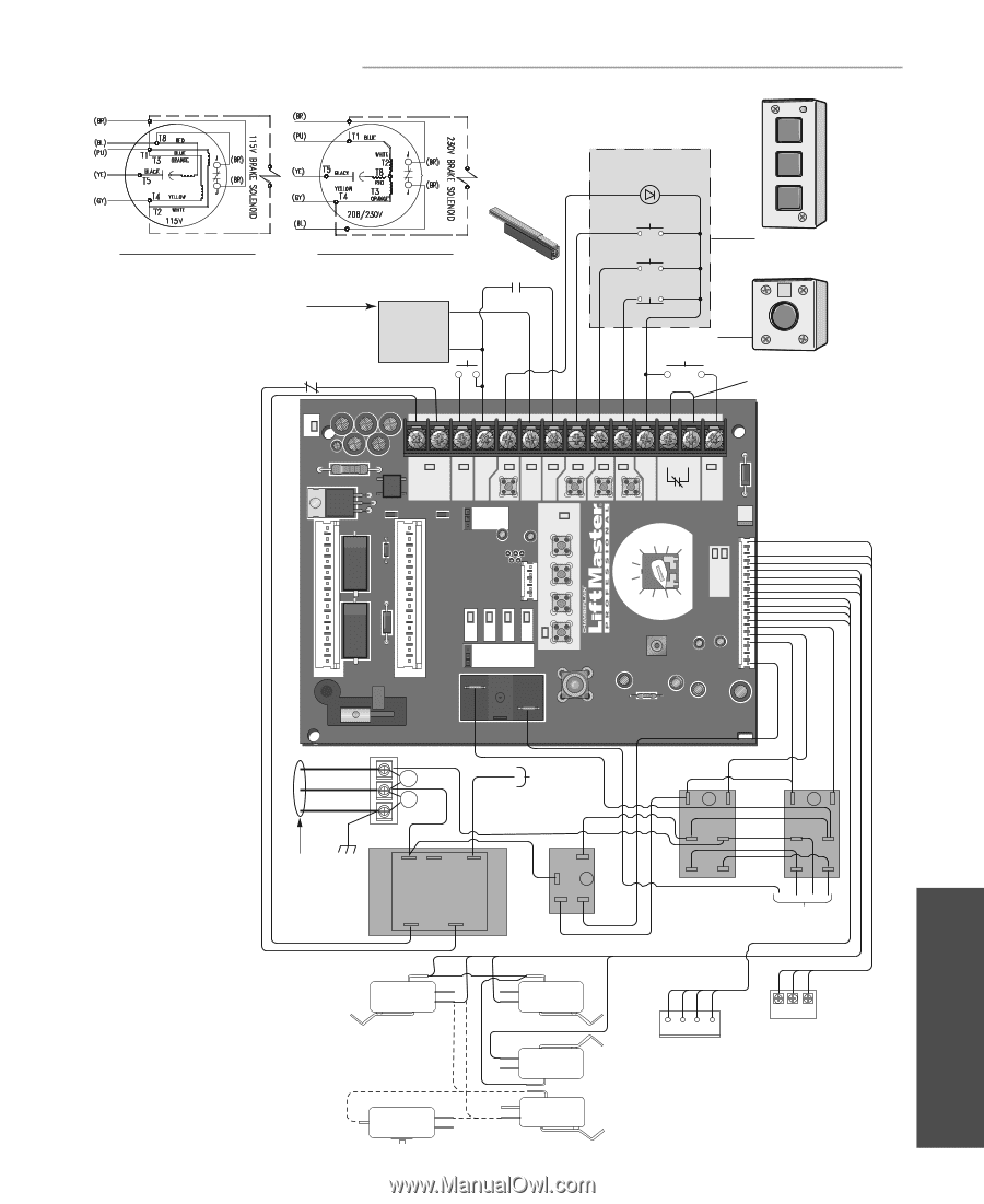
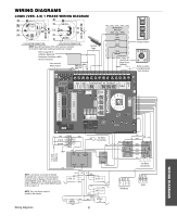
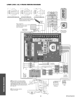
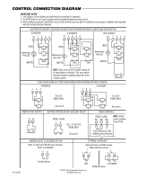
WIRING DIAGRAMS LOGIC (VER. 4.0) 1 PHASE WIRING DIAGRAM 115V MOTOR CONNECTION 230V MOTOR CONNECTION NOTE: Gray (GY) and purple (PU) motor wires are reversed for H and HJ right hand models and all GH and J models. Refer to page 26 for LiftMaster Monitored Entrapment Protection (LMEP) device connections Hoist Interlock When Present TMR DEF (BL) SWITCH (YE) Sensing Edge Maintenance Alert LED (RD) (WH) Open Close Stop OPEN CLOSE STOP 3-Button Station Open/Close Single Button Remove Jumper To Install External Door Interlock DATA C1 C8 C61 SBC STOP COMMON CLOSE OPEN EDGE: LMEP: 24VAC POWER 24VAC TIMER DEFEAT COMMON MAS TIMER ENABLE 3-PHASE 1-PHASE OLS MID SLS SLOT 1 SLOT 2 REV MOTOR DIRECTION STD CLS MRT MID TTC RADIO 1 2 3 T E2 D1 C2 B2 TS FSTS DIAG OPTN PROG RELAY A RELAY B (YE) (OR) (WH) (YE) (PU) (WH) (RD) (GY) (YE) (RD) (WH) (PU) (YE) (OR) (GY) hot neutral ground L3 L2 L1 (BK) MOV MOV (BR) See Motor Connections (WH) 115 / 230 VOLT 1PH. POWER IN (WH) COM 120 120 / 240 VAC VAC (WH) NO COM C (YE) +24 VAC -24 VAC COIL (GY) NOTE: Lock Sensor is provided on Models DJ and DH only, red wire from main harness connects to NC on Bypass L/S and to NO on LOCK SENSOR switch. White wires connect the COM on BYPASS L/S and LOCK SENSOR switch to NC on Open L/S. (WH) (RD) (PU) (WH) COM OPEN L/S NO NC (WH) COM NO CLOSE L/S NC (YE) NOTE: The Lock Sensor switch is located in the chassis. (WH) LOCK (RD) NO SENSOR NC (see note at left) (WH) NC SAFETY L/S NO COM (WH) (RD) NO NC COM BYPASS L/S Wiring Diagrams 41 (WH) 0 B 1 4 8 2 6 (YE) (WH) (OR) (PU) (WH) (WH) (WH) (WH) (WH) 0 A 1 4 8 2 6 (YE) (PU) (BL) (GY) See Motor Connections (WH) (RD) (YE) (GY) (WH) (OR) (YE) 1 2 3 4 RPM Board R1 R2 R3 Radio WIRING DIAGRAMS
-
 1
1 -
2
-
3
-
4
-
5
-
6
-
7
-
8
-
9
-
10
-
11
-
12
-
13
-
14
-
15
-
16
-
17
-
18
-
19
-
20
-
21
-
22
-
23
-
24
-
25
-
26
-
27
-
28
-
29
-
30
-
31
-
32
-
33
-
34
-
35
-
 36
36 -
 37
37 -
 38
38 -
 39
39 -
 40
40 -
 41
41 -
 42
42 -
 43
43 -
 44
44
 |
 |