LiftMaster GH GT- Logic 4 Installation Manual - Page 44
Control Connection Diagram
 |
View all LiftMaster GH manuals
Add to My Manuals
Save this manual to your list of manuals |
Page 44 highlights
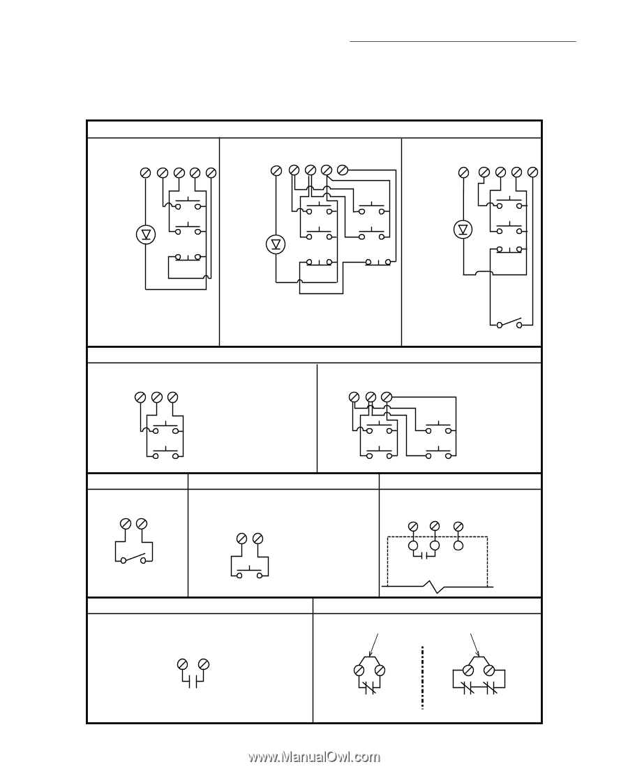
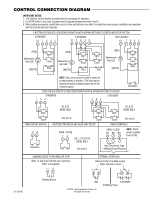
CONTROL CONNECTION DIAGRAM IMPORTANT NOTES: 1. The 3-Button Control Station provided must be connected for operation. 2. If a STOP button is not used, a jumper must be placed between terminals 4 and 5. 3. When adding accessories, install them one at a time and test each one after it is added to ensure proper installation and operation with the Commercial Door Operator. 3 BUTTON STATION OR 3 POSITION KEYSWITCH WITH SPRING RETURN TO CENTER AND STOP BUTTON STANDARD 10 7 6 4 5 2 OR MORE 10 7 6 4 5 KEY LOCKOUT 10 7 6 4 5 (RED) Maintenance Alert LED (WHITE) Open Close Stop (RED) Maintenance Alert LED (WHITE) (RED) Open Open Maintenance Alert LED Close Close Stop Stop (WHITE) Open Close Stop NOTE: Stop circuit must be wired in series for all stop buttons to function. This may require removal of factory installed jumper bar in the 3-button station. 2 BUTTON STATION OR 3 POSITION KEYSWITCH WITH SPRING RETURN TO CENTER STANDARD 764 764 2 OR MORE Keyswitch Open Close TIMER DEFEAT SWITCH 11 12 Keyswitch D1 & E2 MODE ONLY D1 & E2 MODE ONLY Open Open See note 2. Close Close See note 2. 1 BUTTON STATION OR ANY AUXILIARY DEVICE RADIO CONTROLS OPEN / CLOSE 14 B2, T, TS & FSTS MODE ONLY See note 2. OPEN / CLOSE R1 R2 R3 NOTE: 32Vdc power supplied from R1-R3. Any Commercial Type LiftMaster Brand Receiver SENSING DEVICE TO REVERSE OR STOP Note: 11 and 4 are both the same common. Either is acceptable. 11 8 EXTERNAL INTERLOCK Remove Factory Installed Jumper When Interlock is Used 2 3 2 3 01-35241D Sensing Device ONE © 2010, The Chamberlain Group, Inc. All Rights Reserved 2 OR MORE All Wiring Types
-
 1
1 -
2
-
3
-
4
-
5
-
6
-
7
-
8
-
9
-
10
-
11
-
12
-
13
-
14
-
15
-
16
-
17
-
18
-
19
-
20
-
21
-
22
-
23
-
24
-
25
-
26
-
27
-
28
-
29
-
30
-
31
-
32
-
33
-
34
-
35
-
36
-
37
-
38
-
 39
39 -
 40
40 -
 41
41 -
 42
42 -
 43
43 -
 44
44
 |
 |