LiftMaster GH GH-MECHANICAL Manual
LiftMaster GH Manual
 |
View all LiftMaster GH manuals
Add to My Manuals
Save this manual to your list of manuals |
LiftMaster GH manual content summary:
- LiftMaster GH | GH-MECHANICAL Manual - Page 1
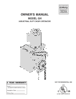
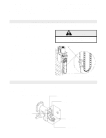
OWNER'S MANUAL MODEL GH INDUSTRIAL DUTY DOOR OPERATOR FACTORY SET C2 Wiring See page 8 for other wiring configurations 2 YEAR WARRANTY Serial # (located on electrical box cover) Installation Date Wiring Type NOT FOR RESIDENTIAL USE 41B6 LISTED DOOR OPERATOR - LiftMaster GH | GH-MECHANICAL Manual - Page 2
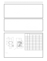
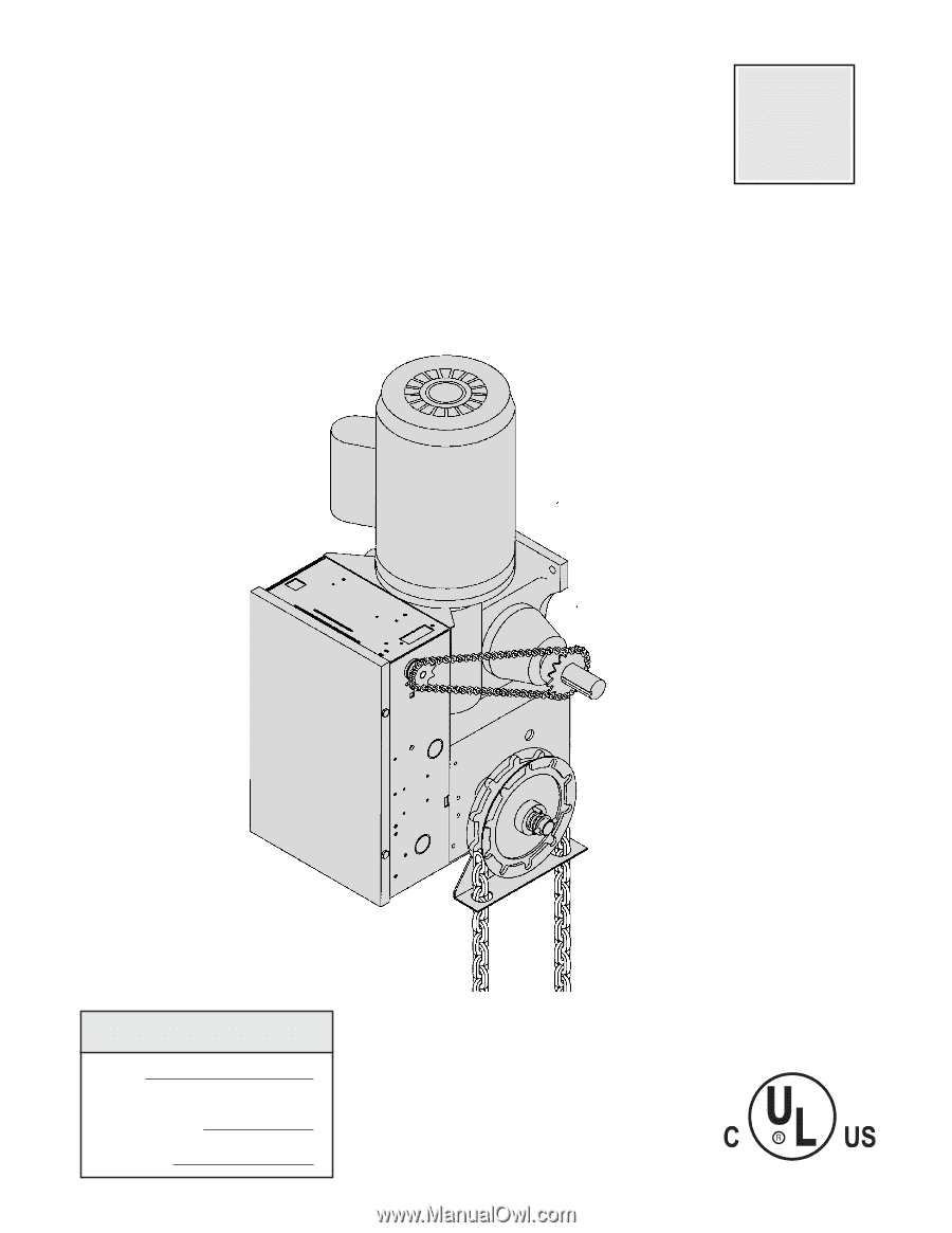
43 R.P.M. DOOR SPEED 4 - 10" per sec. depending on door BRAKE Solenoid actuated disc brake HOIST WHEEL Standard mounting on left or right side SAFETY DISCONNECT Floor level chain hoist with electrical interlock for emergency manual door operation CLUTCH: (optional)....Adjustable torque limiter - LiftMaster GH | GH-MECHANICAL Manual - Page 3
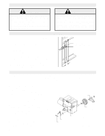
AND OPERATOR, MAKE ALL DOOR LOCKS INOPERATIVE. SECURE LOCK(S) IN "OPEN" POSITION. IF THE DOOR LOCK NEEDS TO REMAIN FUNCTIONAL, INSTALL AN INTERLOCK SWITCH. DO NOT CONNECT ELECTRIC POWER UNTIL INSTRUCTED TO DO SO. KEEP DOOR BALANCED. STICKING OR BINDING DOORS MUST BE REPAIRED. DOORS, DOOR SPRINGS - LiftMaster GH | GH-MECHANICAL Manual - Page 4
on page 3. Refer to the illustration and instructions below that suits your application. 1a. Wall Mounting The operator should generally be installed below the door shaft, and as close to the door as possible. The optimum distance between the door shaft and operator drive shaft is between 12" - 15 - LiftMaster GH | GH-MECHANICAL Manual - Page 5
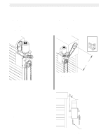
if W necessary. EMERGENCY MANUAL OPERATION This operator has provisions for manually operating the door in case of emergency or power failure. Refer to the appropriate instructions below for your model operator. Model GH These operators are equipped with a manual hoist. An electrical interlock - LiftMaster GH | GH-MECHANICAL Manual - Page 6
please contact your local LiftMaster WIRING: Authorized Dealer. For wiring of your sensing device to the operator, refer to the wiring diagram supplied with your opera- If not pre-installed by the door manufacturer, mount the sensing edge on the door according to the instructions pro- tor. See - LiftMaster GH | GH-MECHANICAL Manual - Page 7
ACCORDANCE WITH LOCAL ELECTRICAL CODES. NOTE: THE OPERATOR as shown below, bring supply lines to the operator SHOULD BE ON A SEPARATE FUSED LINE OF and connect wires to the terminals indicated on the ADEQUATE CAPACITY. CAUTION WARNING WIRING CONNECTIONS DIAGRAM. ALL ELECTRICAL CONNECTIONS MUST - LiftMaster GH | GH-MECHANICAL Manual - Page 8
close the door. SPECIAL CONTROL WIRING If your operator was shipped from the factory with non-standard control wiring or with optional accessories that require addition instructions, refer to the wiring diagram(s) indicated in the special control wiring data box. When a replacement wiring diagram is - LiftMaster GH | GH-MECHANICAL Manual - Page 9
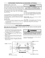
on the FIELD WIRING CONNECTIONS diagram, the control circuit will be disabled when the switch is actuated, thereby preventing electrical operation of the door from the control devices. CLUTCH ADJUSTMENT (OPTIONAL MODIFICATION) 1. Loosen set screws on clutch nut. 2. Back off clutch nut until there - LiftMaster GH | GH-MECHANICAL Manual - Page 10
SERVICING OR ADJUSTING THE OPERATOR. Be sure you have read and understand all Safety Instructions included in this manual. CAUTION Be sure the owner or person(s) responsible for operation of the door have read and understand the Safety Instructions, know how to electrically operate the door - LiftMaster GH | GH-MECHANICAL Manual - Page 11
. „ Do not lubricate motor. Motor bearings are rated for continuous operation. „ Inspect and service whenever a malfunction is observed or suspected. „ CAUTION: BEFORE SERVICING, ALWAYS DISCONNECT OPERATOR FROM POWER SUPPLY. HOW TO ORDER REPAIR PARTS OUR LARGE SERVICE ORGANIZATION SPANS AMERICA - LiftMaster GH | GH-MECHANICAL Manual - Page 12
OVERLOAD (BK) IR (SEE NOTE #1) (BK) 230V MODELS 115V MODELS PUR BL YEL GY BL/BK 1 8 5 23 4 BL/BK 230 VOLT - 1 PHASE MOTOR CONNECTION CL 4 3 OP 4 3 OP 2 1 CL 6 5 OP 5 6 CL 1 2 (YE) (GY) (PUR) TO MOTOR (BL) 3 (YEL) STOP OPEN SAFETY EDGE (OR) R1 (OR) (BR) EXTERNAL - LiftMaster GH | GH-MECHANICAL Manual - Page 13
'D ) 230V. CONNECTION NOTES: 1) TO REVERSE MOTOR DIRECTION: INTERCHANGE PURPLE & GRAY MOTOR LEADS AT CONTACTOR 1 & 3. 2) WIRE MUST BE REMOVED FOR 23OV 1PH OPERATION. **- Transformer Primary & Relay Voltage same as Line Voltage. 1 2 3 4 5 7 10 L1 L2 L3 GROUND OPEN CLOSE STOP EXT. INTLK. TO - LiftMaster GH | GH-MECHANICAL Manual - Page 14
CLOSE CONTROL WIRING OPTIONS *C2 WIRING - Constant Presssure to Close RED WIRE ON TERMINAL #2 (Shipped from Factory) B2 WIRING - Momentary Contact to Close MOVE RED WIRE FROM TERMINAL #2 TO TERMINAL #3 NOTE: 1. Voltage same as line voltage 2. Overload in motor for models up to 3/4 Hp, located in - LiftMaster GH | GH-MECHANICAL Manual - Page 15
BROWN 95 OVERLOAD ( 1 HP & ABOVE ONLY ) RED ORANGE GREY ORANGE PURPLE PURPLE RED ORANGE YELLOW ORANGE BROWN BROWN ORANGE YELLOW YELLOW GREY BLACK BLACK BLACK 1 2 3 4 5 7 10 L1 L2 L3 GROUND OPEN EXT. INTLK. * - Shipped from Factory CLOSE CONTROL WIRING OPTIONS CLOSE TO OPEN AND CLOSE L1 L2 - LiftMaster GH | GH-MECHANICAL Manual - Page 16
specified below. Refer to page 11 for all repair part ordering information. Complete Electrical Box Replacement Kits To order a complete electrical box replacement kit, add a K- prefix to the model number of your operator. For example: GH5011M (Operator) = K-GH5011M (Elec. Box Kit) Electrical Box - LiftMaster GH | GH-MECHANICAL Manual - Page 17
ILLUSTRATED PARTS - ELECTRICAL BOX S6 S5 S2 S7 S1 S8 S4 S9 S3 L3 L1 6 7 1 10 L8 L6 L2 3 11 2 4 17 L7 9 5 L2 L5 L4 8 - LiftMaster GH | GH-MECHANICAL Manual - Page 18
12586 OPERATOR(S) 115 Volt Models 230-460 Volt Models 575 Volt Models ITEM B1 B2 B3 B4 B5 B6 B7 B8 B9 B10 B11 PART # 07-10179 10-10190 10-10191 11-10192 11-10193 18-10194 31-10186 75-10184 75-11034 75-11035 75-11036 80-9001 87-P-062 DESCRIPTION Brake Hub Brake Release Lever Brake Disk Spring Cup - LiftMaster GH | GH-MECHANICAL Manual - Page 19
4 5 6 1 B10 D4 D11 D9 D12 D15 D16 D8 D5 D15 D13 D3 D7 D6 D1 D2 D10 H15 H9 H6 ILLUSTRATED PARTS - MODEL GH 19 2 3 G2 D13 H13 H12 G1 H9 H4 H5 H15 B9 D15 D14 H15 H2 H9 H5 B7 H15 B3 B2 G3 H3 H8 B1 B4 B6 B5 H11 H7 B8 B11 H14 H1 H10 - LiftMaster GH | GH-MECHANICAL Manual - Page 20
TO REVERSE OR STOP RESIDENTIAL RADIO CONTROLS 3 10 *OPEN TIMER TO CLOSE R1 R2 R3 EXTERNAL TERMINAL BLOCK Sensing Device RADIO CONTROL ALL CONTROL WIRING TYPES TIMER TO CLOSE w/ WARNING LIGHT Warning Light will activate 15 sec. before door closes. 11 12 13 14 Auxiliary Terminal Block Timer
-
 1
1 -
 2
2 -
 3
3 -
 4
4 -
 5
5 -
 6
6 -
 7
7 -
8
-
9
-
10
-
11
-
12
-
13
-
14
-
15
-
16
-
17
-
18
-
19
-
20
 |
 |
OWNER'S MANUAL
MODEL GH
INDUSTRIAL DUTY DOOR OPERATOR
Serial #
(located on electrical box cover)
Installation Date
Wiring Type
2 YEAR WARRANTY
C2 Wiring
FACTORY SET
See page 8 for
other wiring
configurations
NOT FOR RESIDENTIAL USE
LISTED
DOOR
OPERATOR
41B6