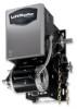
LiftMaster H GT- Logic 4 Installation Manual
LiftMaster H Manual
 |
View all LiftMaster H manuals
Add to My Manuals
Save this manual to your list of manuals |
LiftMaster H manual content summary:
- LiftMaster H | GT- Logic 4 Installation Manual - Page 1
HJ T AND APT L 4 ogic L3 GH THIS PRODUCT IS TO BE INSTALLED AND SERVICED BY A TRAINED DOOR SYSTEMS TECHNICIAN ONLY. Operators are shipped in C2 operating mode. Visit www.liftmaster.com to locate a professional installing dealer in your area. CONTACT INFORMATION GT 2 YEAR WARRANTY Serial # Box - LiftMaster H | GT- Logic 4 Installation Manual - Page 2
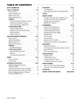
System Model GT and T 26 Emergency Disconnect System Model APT 26 Emergency Disconnect System Model H, GH, J, and HJ 27 PROGRAMMING 28-35 Introduction to Programming 28 Determine and Set Wiring Type 29 Programming Remote Controls 30-31 Maintenance Alert System (MAS 32 Open Mid - LiftMaster H | GT- Logic 4 Installation Manual - Page 3
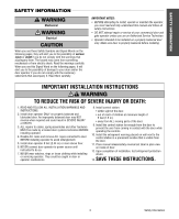
to install, operate or maintain the operator, you must read and fully understand this manual and follow all safety instructions. WARNING • DO NOT attempt repair or service of your commercial door and WARNING gate operator unless you are an Authorized Service Technician. • Operator intended to be - LiftMaster H | GT- Logic 4 Installation Manual - Page 4
assembly Owner's manual and caution labels Hardware box (includes fasteners, track spacers, trolley, door arm assembly, front idler and header mounting bracket) 3-Button control station with LED Trolley drive chain: #48 for 1/3 and 1/2 HP, #41 for 3/4 HP and higher (all GT models) Entrapment - LiftMaster H | GT- Logic 4 Installation Manual - Page 5
1 HP Model T ONLY) Model GT Primary: 20:1 Heavy duty worm gear-in-oil-bath speed reducer Output: #41 chain OUTPUT SHAFT SPEED: Model APT 96 RPM Model GT 113.5 RPM Model T 140 RPM DOOR SPEED (not adjustable): Model APT 6-7" per second Model GT 11-12" per second Model T 11-12" per second BRAKE - LiftMaster H | GT- Logic 4 Installation Manual - Page 6
Travel 11.63" (29.54 cm) *23.43" (59.51 cm) *- For Units with Brake add 3-1/2" (Standard on APT, T 3/4 and T 1 HP models; Optional on T 1/3 and 1/2 HP models) MODEL GT Hanging Weight: 140 lbs. 4" (10.16 cm) Door Height Plus 4 feet (minimum) 13.05" (33.15 cm) * 17.5" (44.45 cm) 18.5" (46.99 - LiftMaster H | GT- Logic 4 Installation Manual - Page 7
TROLLEY ASSEMBLY ASSEMBLE THE OPERATOR (MODELS T AND GT) NOTE: For Model APT assembly refer to page 9. 1 bolts (F) and washers (D). 3 Assemble the trolley with the take up bolt (C), hex nuts (E), and lock washer (D). 4 Slide the trolley onto the track. 5 Insert bolts (A) into the end of the track - LiftMaster H | GT- Logic 4 Installation Manual - Page 8
TROLLEY INSTALL THE CHAIN (MODELS T AND GT) NOTE: For Model APT assembly refer to page 9. 1 Position the trolley 2 inches away from the front idler. 2 Attach the chain to the trolley threaded shaft using the master link. 3 Run the chain along the track to the operator. Wrap the chain around the - LiftMaster H | GT- Logic 4 Installation Manual - Page 9
TROLLEY ASSEMBLE THE OPERATOR (MODEL APT) NOTE: If your model is not an APT, proceed to the 3/4" B Flange Hex Nut 3/8"-16 3 8 Slide the trolley onto the track so the door arm hole faces the front (towards the door). Pull the release clip on the trolley and push the end of the chain through the - LiftMaster H | GT- Logic 4 Installation Manual - Page 10
location of door stile / top section support. Typically, the operator may be mounted up to 24 inches off center on torsion spring doors. Extension springs require center mounting. 1 Close the door. Mark the center of the door with a vertical line, extend the line onto the ceiling. 2 Open the door to - LiftMaster H | GT- Logic 4 Installation Manual - Page 11
3 WARNING HANG THE OPERATOR 1 Secure the operator using the appropriate fasteners and locking hardware that will support the weight of the operator. CAUTION To avoid possible SERIOUS INJURY from a falling operator: • Fasten the operator SECURELY to structural supports of the building. • Concrete - LiftMaster H | GT- Logic 4 Installation Manual - Page 12
using appropriate hardware (not included). NOTE: When properly installed and adjusted the door arm should be leaning back toward the operator slightly. Refer to door manufacturer's instructions for recommended installation guidelines. HARDWARE A Flanged Hex Nut 3/8"-16 (2) B Nylok Nut 3/8"-16 - LiftMaster H | GT- Logic 4 Installation Manual - Page 13
disconnect for manual door operation Model H and GH Floor level chain hoist with electrical interlock for manual door operation Model HJ Includes both floor level disconnect systems stated above ENTRAPMENT PROTECTION: LiftMaster Monitored Entrapment Protection (LMEP) Photoelectric Sensors (CPS - LiftMaster H | GT- Logic 4 Installation Manual - Page 14
#50 chain OUTPUT SHAFT SPEED: Model J, H and HJ 36 RPM Model GH 38.3 for 1/2, 3/4 and 1 HP 39.2 for 1-1/2 and 2 HP 41.1 for 3 HP DOOR SPEED: Model J, H and HJ 8-9" per second depending on door Model GH 8-9" per second depending on door BRAKE Solenoid actuated disc brake BEARINGS Output Shaft - LiftMaster H | GT- Logic 4 Installation Manual - Page 15
(rolling door) 3/8" Bolt 7.56" (19.2 cm) 4.41" (11.2 cm) 6.59" A (16.74 cm) B 5.5" (14 cm) 1.5" (3.81 cm) A B 13.75" (34.93 cm) B B 16.43" (41.73 cm) *23.43" A A (59.51 cm) Hand Chain Wheel Present with Models H and HJ ONLY 4.56" (11.58 cm) HOIST AND JACKSHAFT MODEL GH Hanging - LiftMaster H | GT- Logic 4 Installation Manual - Page 16
manual hand chain systems, the handing of the operator must be determined at the time of order. The handing is indicated by the last letter of the model number (R or L). The hand chain wheel cannot be switched. If your ATTENTION installation causes the hand chain to hang in the door opening, hook - LiftMaster H | GT- Logic 4 Installation Manual - Page 17
MOUNTING 1 Place the door sprocket on the door shaft. 2 Place the operator drive sprocket on the appropriate side of the operator for your installation type. 3 Wrap the drive chain around the door sprocket and the drive sprocket then secure with the master link. 4 Align the door and the drive - LiftMaster H | GT- Logic 4 Installation Manual - Page 18
operator or in the area near the operator MUST NOT be performed until disconnecting the electrical power and locking control wiring MUST be run in separate conduit. POWER AND GROUND Power and control wiring the safety limit switch (SLS) to the opposite side. 3. Remove CLOSE/OPEN decal and reattach - LiftMaster H | GT- Logic 4 Installation Manual - Page 19
and away from ALL moving parts of door. • Install the entrapment warning placard on wall next to the control station in a prominent location that is visible from the door. • NEVER permit children to operate or play with door control push buttons or remote controls. • Activate door ONLY when it can - LiftMaster H | GT- Logic 4 Installation Manual - Page 20
SERIOUS INJURY or DEATH from a closing door: • Be sure power is NOT connected to the door operator BEFORE installing the photoelectric sensor. • The door MUST be in the fully opened or closed position BEFORE installing the LiftMaster Monitored Entrapment Protection device. To prevent SERIOUS - LiftMaster H | GT- Logic 4 Installation Manual - Page 21
shown. Note alignment of brackets for left and right sides of the door. 3 Finger tighten the lock nuts. 4 Use bracket mounting holes as a template to locate and drill (2) 3/16" diameter pilot holes on both sides of the garage door, 4-6 inches (10-15 cm) above the floor. Do not exceed 6 inches (15 - LiftMaster H | GT- Logic 4 Installation Manual - Page 22
Secure wire with insulated staples Connect wire to Operator (refer to following page) Photoelectric Sensor 6" (15 cm) max. above floor Invisible Light Beam Protection Area Photoelectric Sensor 6" (15 cm) max. above floor WIRE THE LIFTMASTER MONITORED ENTRAPMENT PROTECTION (LMEP) DEVICES 1 Connect the - LiftMaster H | GT- Logic 4 Installation Manual - Page 23
SEVERE INJURY OR DEATH: 1. READ AND FOLLOW ALL WARNINGS AND INSTRUCTIONS. 2. ALWAYS keep remote controls out of reach of children. NEVER permit children to operate or play with door control push buttons or remote controls. 3. ONLY activate door when it can be seen clearly, it is properly adjusted - LiftMaster H | GT- Logic 4 Installation Manual - Page 24
centrifugal switch on single phase motors, the leading cause of motor failures is eliminated. (Auxiliary Reversal System not applicable on models GH and GT.) NOTE: This feature is automatically learned and does not require programming. Adjustment - Clutch adjustment 24 LOSE OPEN RPM Sensor Logic - LiftMaster H | GT- Logic 4 Installation Manual - Page 25
all safety instructions included in this manual. • Be sure the owner or person(s) responsible for operation of the door have read and understand the safety instructions, know how to electrically operate the door in a safe manner and how to manually disconnect the door from the operator. 25 Testing - LiftMaster H | GT- Logic 4 Installation Manual - Page 26
MANUAL RELEASE EMERGENCY DISCONNECT SYSTEM MODEL GT AND T TO DISCONNECT DOOR FROM OPERATOR The door should be in the fully closed position if possible. 1 Pull emergency release handle straight down. Emergency disconnect will open. TO RECONNECT DOOR ARM TO TROLLEY 2 Lift free end of door arm to - LiftMaster H | GT- Logic 4 Installation Manual - Page 27
provisions for manually operating the door in case of emergency or power failure. Refer to the appropriate instructions below for your model operator. MODEL H AND GH These operators are equipped with a manual hoist. An electrical interlock will disable the electrical controls when the hoist is used - LiftMaster H | GT- Logic 4 Installation Manual - Page 28
is activated the corresponding LED will light up. The abbreviations are Open Limit Switch (OLS), Close Limit Switch (CLS) and Sensing Limit Switch (SLS). Refer to page 19 for limit switch adjustment instructions. When power is applied to the operator, the following LED's will illuminate: STOP, CLOSE - LiftMaster H | GT- Logic 4 Installation Manual - Page 29
until the door reaches the down limit, or is stopped in travel. At which time the operator enters the B2 mode. Compatible with 3-Button Station, 1-Button Station, 1 and 3-Button Remote Control. A 1-Button remote control in FSTS mode will open only with the Timer-To-Close, bypassing a programmed mid - LiftMaster H | GT- Logic 4 Installation Manual - Page 30
permit anyone to cross the path of closing door. W W Built in 3-channel, 315 MHz radio receiver allows you to add as many as 23 Security® remotes or dip switch remote controls. NOTE: The following programming requires a LiftMaster Monitored Entrapment Protection (LMEP) device. NOTICE: To comply - LiftMaster H | GT- Logic 4 Installation Manual - Page 31
PROGRAMMING REMOTE CONTROLS NOTE: The following programming requires a LiftMaster Monitored Entrapment Protection (LMEP) device. Your 315 MHz Security✚® or dip switch remote control can be programmed to operate as a 3-button wireless control station: the large button will open the door, the middle - LiftMaster H | GT- Logic 4 Installation Manual - Page 32
. Turn to page 35 to diagnose problem. Example: A door is installed with 30,000 cycle springs and has an annual service contract. To set the MAS, turn selector dial to PROGRAM, press MAS button, press the STOP button to clear the memory and then press the OPEN button 6 times (30,000 cycles) and - LiftMaster H | GT- Logic 4 Installation Manual - Page 33
push buttons or remote controls. permit anyone to cross path of closing door. WA W TIMER-TO-CLOSE Feature: Timer automatically closes door after preset time. All 6. Press and release the TIMER button to complete programming. safety devices must be unobstructed. The OPEN/CLOSE button LEDs - LiftMaster H | GT- Logic 4 Installation Manual - Page 34
TS FSTS DIAG OPTN PROG Operation will vary depending on wiring type T E2 D1 C2 B2 TS FSTS DIAG OPTN PROG PROGRAMMING CAR DEALER MODE Feature: The car dealer mode uses the SBC (Single Button Control input) to bring the door from a closed position to the programmed Open Mid-Stop position and keep - LiftMaster H | GT- Logic 4 Installation Manual - Page 35
deactivated f. The remote controls will still be learned g. Remote control programming via the 3-button station h. The LiftMaster Monitored Entrapment Protection (LMEP) device will be unprogrammed NOTE: Life of Operator feature (Odometer/Cycle Counter) and programmed remote controls are not cleared - LiftMaster H | GT- Logic 4 Installation Manual - Page 36
and adjust as required. BeAlt TTENTION Check condition and tension. Fasteners Check and tighten as required. Manual Disconnect Check and operate. Bearings and Shafts LiftMaster Monitored Entrapment Protection (LMEP) Check for wear and lubricate. Check alignment and functionality. EVERY MONTH - LiftMaster H | GT- Logic 4 Installation Manual - Page 37
assist in the installation and troubleshooting of the operator. The following chart should assist in verifying the operator is functioning properly. Turn the selector dial to DIAGNOSTIC to keep the door from moving while troubleshooting. LED Power Stop Open COLOR Green Green Yellow Close Yellow - LiftMaster H | GT- Logic 4 Installation Manual - Page 38
TROUBLESHOOTING GUIDE FAULT THE OPERATOR WILL NOT RESPOND TO ANY COMMANDS POSSIBLE CAUSE FIX a) No power supply b) Operator control station is wired wrong c) Interlock switch is activated d) Dial still in programming, option, or diagnostic mode e) Motor is malfunctioning f) Motor thermal - LiftMaster H | GT- Logic 4 Installation Manual - Page 39
troubleshoot some problems with the operator. sensor, move the door with a constant pressure command. The door will stop once relearned and normal operation will resume. The door stops before reaching set open or close limit(s) First check Operator for any faults (i.e., Bad Limit switch), manually - LiftMaster H | GT- Logic 4 Installation Manual - Page 40
TROUBLESHOOTING RADIO FUNCTIONALITY The error codes will display at the radio LED. NOTE: Radio receiver is compatible with 315 MHz remotes. ERROR CODE DISPLAY SYMPTOM POSSIBLE PROBLEM CORRECTION R1 Quick Flash No response from the remote Unlearned remote - Try re-learning the A user tries - LiftMaster H | GT- Logic 4 Installation Manual - Page 41
and HJ right hand models and all GH and J models. Refer to page 26 for LiftMaster Monitored Entrapment Protection (LMEP) device connections Hoist Interlock When Present TMR DEF (BL) SWITCH (YE) Sensing Edge Maintenance Alert LED (RD) (WH) Open Close Stop OPEN CLOSE STOP 3-Button Station - LiftMaster H | GT- Logic 4 Installation Manual - Page 42
and HJ right hand models and all GH and J models. Sensing Edge Refer to page 26 for LiftMaster Monitored Entrapment Protection (LMEP) device connections Hoist Interlock When Present TMR DEF (BL) SWITCH (YE) Maintenance Alert LED (RD) (WH) Open Close Stop OPEN CLOSE STOP 3-Button Station - LiftMaster H | GT- Logic 4 Installation Manual - Page 43
1-Button SECURITY✚® Remote Control: Includes visor clip. 3-Button SECURITY✚® Remote Control: CPS-U OPEN Commercial Protector System®: Provides protection on doors up to 30' wide. 333LM WPB1LM3 OPEN WPB3LM3 Includes visor clip. 3-Button Tri-Colored Dip Switch Remote Control: Includes visor clip - LiftMaster H | GT- Logic 4 Installation Manual - Page 44
it is added to ensure proper installation and operation with the Commercial Door Operator. 3 BUTTON STATION OR 3 POSITION KEYSWITCH WITH CONTROLS OPEN / CLOSE 14 B2, T, TS & FSTS MODE ONLY See note 2. OPEN / CLOSE R1 R2 R3 NOTE: 32Vdc power supplied from R1-R3. Any Commercial Type LiftMaster
-
 1
1 -
 2
2 -
 3
3 -
 4
4 -
 5
5 -
 6
6 -
 7
7 -
8
-
9
-
10
-
11
-
12
-
13
-
14
-
15
-
16
-
17
-
18
-
19
-
20
-
21
-
22
-
23
-
24
-
25
-
26
-
27
-
28
-
29
-
30
-
31
-
32
-
33
-
34
-
35
-
36
-
37
-
38
-
39
-
40
-
41
-
42
-
43
-
44
 |
 |
ogic
L
4
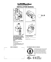
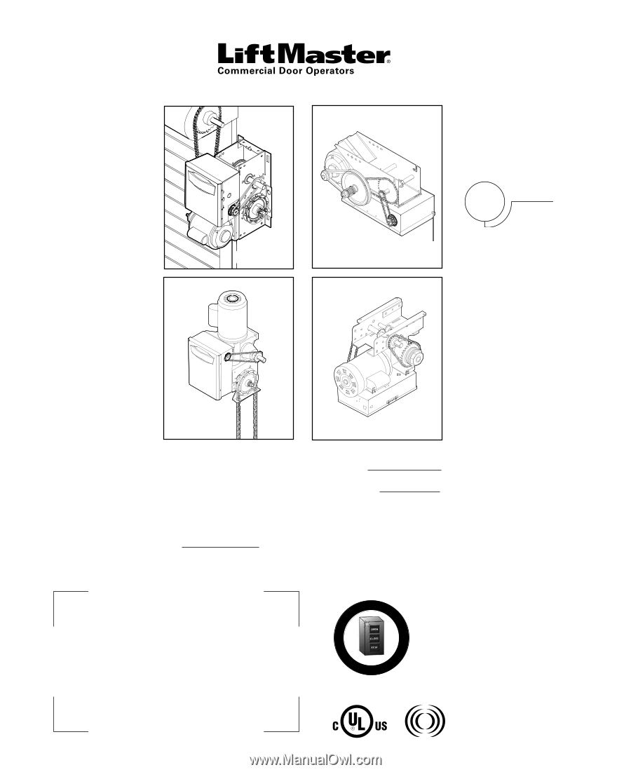
INSTALLATION MANUAL
GT
T AND APT
H, J, AND HJ
GH
A
L
E
R
T
S
Y
S
T
E
M
M
A
I
N
T
E
N
A
N
C
E
PATENT PENDING
The Maintenance Alert System™ allows the installer
to set an internal Maintenance Cycle Counter. The
Logic 4 operator incorporates a self-diagnostic
feature built into the (MAS) Maintenance Alert
System LED. An LED on the 3-button station will
signal when the set number of cycles/months is
reached or when the operator requires immediate
service.
THIS OPERATOR FEATURES THE ENHANCED
Radio Receiver
Built on Board
315MHz
NOT FOR RESIDENTIAL USE
Serial # Box
Installation Date
2 YEAR WARRANTY
THIS PRODUCT IS TO BE
INSTALLED AND SERVICED
BY A TRAINED DOOR
SYSTEMS TECHNICIAN
ONLY.
Operators are shipped in C2
operating mode.
Visit www.liftmaster.com to locate
a professional installing dealer in
your area.
CONTACT INFORMATION