LiftMaster HCTDCU HCTDCU Quick Start Guide Manual
LiftMaster HCTDCU Manual
 |
View all LiftMaster HCTDCU manuals
Add to My Manuals
Save this manual to your list of manuals |
LiftMaster HCTDCU manual content summary:
- LiftMaster HCTDCU | HCTDCU Quick Start Guide Manual - Page 1
Model HCTDCU QuickStart for single gate/door application HCTDCU Motor Unit HCT08 8 Foot Rail HCT10 10 Foot Rail HCT12 12 Foot Rail 2016 UL 325 Gate Operators require use of LiftMaster external monitored entrapment protection devices. This QuickStart is intended to highlight a single gate/door - LiftMaster HCTDCU | HCTDCU Quick Start Guide Manual - Page 2
operator can be wired for 120 or 240 Vac by choosing the desired power wiring socket on the EMI board. Refer to your manual for complete wiring information. Set Open Speed The HCTDCU the TEST BUTTONS. 2. operator is left running on battery only, it will drain the battery and will result in a service - LiftMaster HCTDCU | HCTDCU Quick Start Guide Manual - Page 3
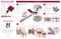
HCTDCU Moteur HCT08 Rail de 2,44 m (8 pi) HCT10 Rail de 3,05 m (10 pi) HCT12 Rail de 3,66 m (12 pi) Les actionneurs de barrière UL 325 2016 exigent l'utilisation de dispositifs externes surveillés de protection de LiftMaster le support de linteau dans l'ouverture et boulonner ou souder le support de - LiftMaster HCTDCU | HCTDCU Quick Start Guide Manual - Page 4
externe surveillé de protection de LiftMaster contre le piégeage (capteur instructions complètes de câblage. Régler la vitesse d'ouverture Le modèle HCTDCU des boutons de mise à l'essai (TEST BUTTONS). 2. Si la barrière/porte s'arrê qui entraînera un appel de service. Vérifier les batteries et leurs - LiftMaster HCTDCU | HCTDCU Quick Start Guide Manual - Page 5
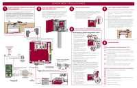
HCTDCU Motor HCT08 Guía de 8 pies HCT10 Guía de 10 pies HCT12 Guía de 12 pies Con los operadores de portón UL 325 2016 es necesario utilizar dispositivos externos monitoreados de protección de LiftMaster de cadena. Tensor 7 Parte superior de guía Tuerca hexagonal bolsa con el manual). 3 Ajustar el - LiftMaster HCTDCU | HCTDCU Quick Start Guide Manual - Page 6
pero ES NECESARIO instalar otra protección externa monitoreada de LiftMaster para CADA zona de atrapamiento (sensor fotoeléctrico sin la tarjeta EMI. Consultar el manual para obtener las instrucciones completas de cableado. Fijar velocidad de apertura El HCTDCU ofrece la opción de apertura
-
 1
1 -
 2
2 -
 3
3 -
 4
4 -
 5
5 -
 6
6
 |
 |
1
3
4
5
6
2
7
1
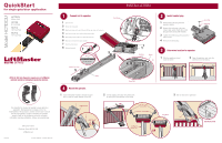
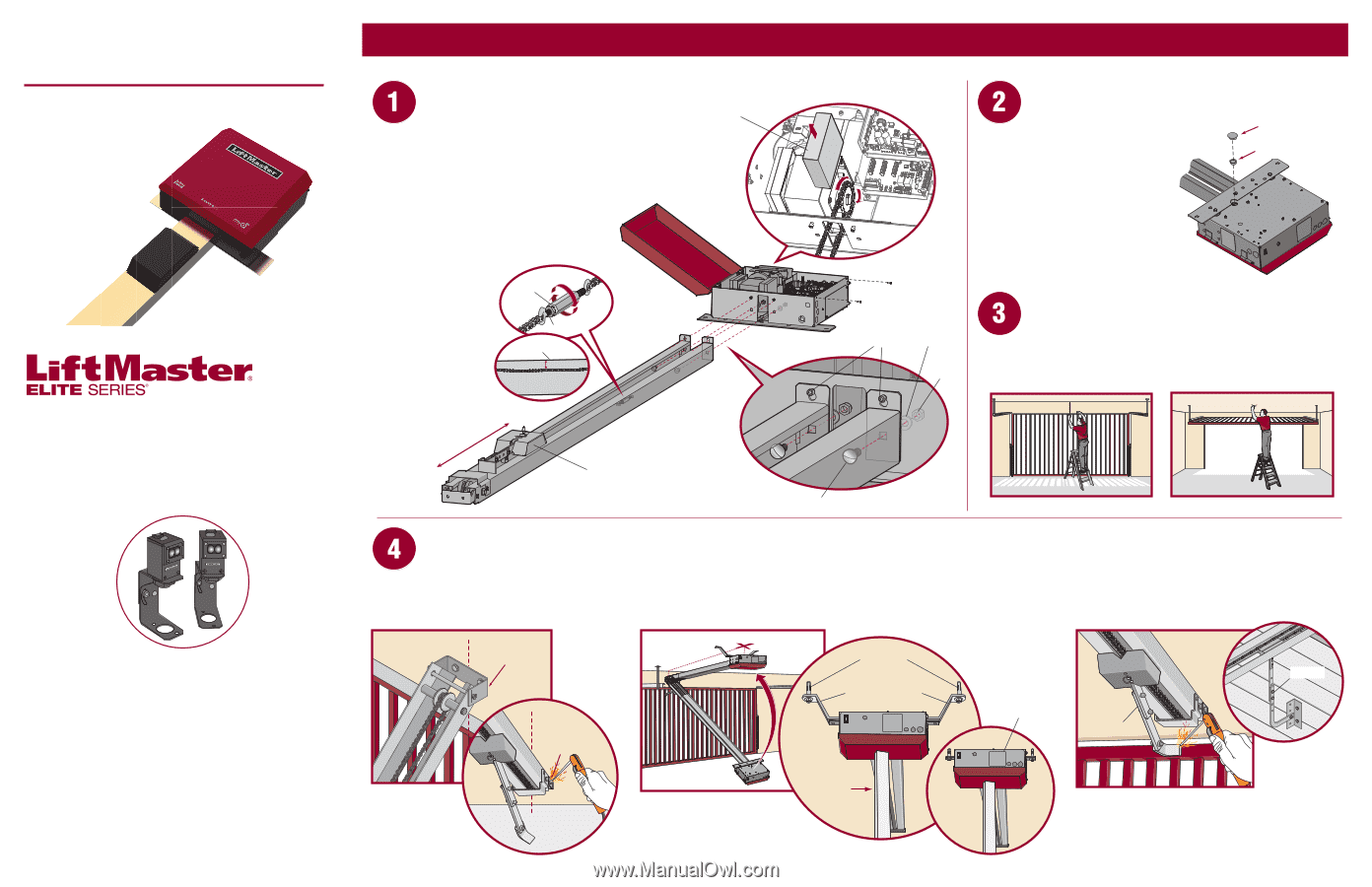
Open the cover.
2
Remove the chain guard.
3
Align the key holes on the end of the rail with the cap screws on the chassis.
4
Attach the rail to the chassis with the hardware provided.
5
Move trolley to within 3 feet (.9 m) of the end of the rail.
6
Wrap the chain around the output sprocket.
7
Adjust the chain tension.
8
Replace chain guard.
This QuickStart is intended to highlight a single gate/door
application. Each application is unique and it is the
responsibility of the purchaser, installer and end user to ensure
that the total gate/door system is installed and operated
properly. Refer to the installation manual for complete
information regarding installation, testing, and programming.
QuickStart
for single gate/door application
Model HCTDCU
INSTALLATION
01-38474
© 2016, LiftMaster – All Rights Reserved
845 Larch Avenue
Elmhurst, Illinois 60126-1196
LiftMaster.com
Connect rail to operator.
Install vented plug.
Determine location for operator.
Mount the operator.
2016 UL 325 Gate Operators require use of LiftMaster
external monitored entrapment protection devices.
HCTDCU
Motor Unit
HCT08
8 Foot Rail
HCT10
10 Foot Rail
HCT12
12 Foot Rail
Temporary
Support Post
Header Bracket
Vented Plug
Header Bracket
OR
Concrete Anchor
1/2" x 3 1/2"
Brackets (not provided)
Flush Mount
Arm
Door Arm
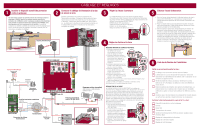
DOOR INSTALLATION
Cap Screw
Chain Guard
Trolley
Within 3 feet (.9 m)
Top of Rail
1/4" (.64 cm) Max.
Turnbuckle
Hex Nut
Carriage Bolt
Nut
Washer
1
Center the header bracket in the opening and
bolt or weld the header bracket to the wall.
2
Lift the operator and align with center mark
on ceiling. Bolt the operator to the ceiling.
3
Bolt or weld arm to gate/door.
1
With the gate/door closed,
mark the center.
1
Remove the dome plug from the
operator chassis.
2
Remove the solid plug in the gear
reducer and replace it with the vented
plug (provided in bag with manual).
3
Tighten the vented plug with a socket or
Allen wrench.
4
Re-insert the dome plug.
2
Open the gate/door and mark the
center point on the ceiling.
Dome Plug