LiftMaster J J- LOGIC 3 Manual
LiftMaster J Manual
 |
View all LiftMaster J manuals
Add to My Manuals
Save this manual to your list of manuals |
LiftMaster J manual content summary:
- LiftMaster J | J- LOGIC 3 Manual - Page 1
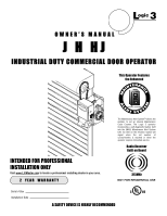
L 3 ogic OWNER'S MANUAL J H HJ INDUSTRIAL DUTY COMMERCIAL DOOR OPERATOR This Operator Features the Enhanced INTENAN M A E M E C AL INTENDED FOR PROFESSIONAL INSTALLATION ONLY Visit www.LiftMaster.com to locate a professional installing dealer in your area. 2 YEAR WARRANTY E PATENT PENDING R T - LiftMaster J | J- LOGIC 3 Manual - Page 2
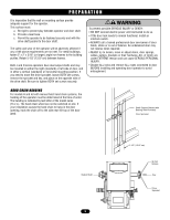
NOTES: WWAARRNNININGG • BEFORE attempting to install, operate or maintain the operator, you must read and fully understand this manual and follow all safety instructions. • DO NOT attempt installation, repair or service of your WARNING commercial door and gate operator unless you are an Authorized - LiftMaster J | J- LOGIC 3 Manual - Page 3
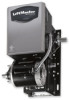
your installation check that all components were provided. DESCRIPTION POWERHEAD ASSEMBLY OWNER'S MANUAL AND CAUTION LABELS HARDWARE BOX (INCLUDES FASTENERS, DISCONNECT AND CHAIN HOIST WALL BRACKET) 3-BUTTON CONTROL STATION WITH LED HOIST HAND CHAIN (MODELS H AND HJ ONLY) DOOR SPROCKET DOOR/OPERATOR - LiftMaster J | J- LOGIC 3 Manual - Page 4
with open override. See pages 16 and 17 for optional wiring types and operating modes. LIMIT ADJUST Linear driven, fully adjustable screw type cams. MECHANICAL DRIVE REDUCTION Primary: Heavy duty (5L) V-Belt Secondary: #48 chain/sprocket; Output: #50 chain OUTPUT SHAFT SPEED 36 RPM DOOR SPEED - LiftMaster J | J- LOGIC 3 Manual - Page 5
manual hoist hand chain systems, the handing of the operator must be determined at the time of order. The handing is indicated by last letter of the model name (R or L). The hand chain wheel can not be switched on site. If your installation causes the hand chain to hang in the door opening, hook - LiftMaster J | J- LOGIC 3 Manual - Page 6
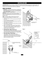
to door shaft and sprockets are aligned. When in position, secure the operator to wall or mounting bracket. 7. Align sprockets and secure (Figure 3). 8. Install Hand Chain (Models H and HJ only) Place hand chain around hand chain wheel. Be sure to pass it through both openings in the chain guide - LiftMaster J | J- LOGIC 3 Manual - Page 7
disconnect chain to disconnect the door from the door operator and a disconnect chain with manual hoist to electrically disable the operator controls. 1. Refer to Model H instructions for hoist operation. 2. Refer to Model J instructions for manual operation. Electrical Interlock with Hoist for - LiftMaster J | J- LOGIC 3 Manual - Page 8
the 3-button control station is out of sight of door or ANY other control (automatic or manual) is used. Reversing devices are recommended for ALL installations. WIRING For wiring of your sensing device to the operator, refer to the wiring diagrams provided on pages 13 and 14. See field connection - LiftMaster J | J- LOGIC 3 Manual - Page 9
closing or stops the door when opening. 1. Remove cotterpin from nut on the clutch shaft. 2. Back off clutch nut until there is very little tension on the clutch spring. 3. Tighten clutch nut gradually until there is just enough tension to permit the operator to move the door smoothly but to allow - LiftMaster J | J- LOGIC 3 Manual - Page 10
made by a qualified individual. • DO NOT install ANY wiring or attempt to run the operator without consulting the wiring diagram. We recommend that you install an optional reversing edge BEFORE proceeding with the control station installation. • ALL power wiring should be on a dedicated circuit and - LiftMaster J | J- LOGIC 3 Manual - Page 11
a fully closed door, close a fully open door, stop an opening door, and reverse a closing door from the radio remote. In TS control wiring the operator will only open the door or reset the timer to close. However, for additional door control from a 3-button remote control, a commercial three-channel - LiftMaster J | J- LOGIC 3 Manual - Page 12
CONNECTION DIAGRAMS Radio Control (24V DC only) CPS-L & CPS-LN4 R3 R2 R1 Sensing Edge Timer Defeat Switch Maintenance Alert LED (RD) (WH) Open Close Stop Open/Close Single Button OPEN CLOSE STOP 3-Button Station Remove Jumper To Install External Interlock Single Phase Power Wiring Line - LiftMaster J | J- LOGIC 3 Manual - Page 13
DIAGRAM 115V MOTOR CONNECTION 230V MOTOR CONNECTION NOTE: Gray (GY) and purple (PU) motor wires are reversed for H and HJ right hand models and all GH and J models. CPS-L & CPS-LN4 Sensing Edge Hoist Interlock When Present TMR DEF SWITCH (YE) (BL) Maintenance Alert LED (RD) (WH) Open - LiftMaster J | J- LOGIC 3 Manual - Page 14
) and purple (PU) motor wires are reversed for H and HJ right hand models and all GH and J models. Sensing Edge CPS-L & CPS-LN4 Hoist Interlock When Present TMR DEF SWITCH (YE) (BL) Maintenance Alert LED (RD) (WH) Open Close Stop OPEN CLOSE STOP 3-Button Station Open/Close Single Button - LiftMaster J | J- LOGIC 3 Manual - Page 15
D34 MAS 10 EYES 9 EDGE 8 OPEN 7 CLOSE 6 STOP 5 CMN 4 3 2 SBC 1 F1 C54 C71 C78 ® Motor Direction Jumper Single Phase and Three Phase Jumper Maintenance Alert System Button for Programming Open Button Close Button Stop Button Control Wiring Terminal Block Wiring Type Selector Dial Failsafe Switch - LiftMaster J | J- LOGIC 3 Manual - Page 16
LOGIC CONTROL PUSHBUTTONS OPEN, CLOSE, STOP Open, Close and Stop buttons are mounted directly on the logic board. Thus, making it easy to program as well as have door control at the electrical box. Either the stop control or a jumper must be wired between terminals 4 and 5 for the on board - LiftMaster J | J- LOGIC 3 Manual - Page 17
stop with this wiring type. Compatible with 3-Button Station, 1-Button Station and 1- and 3-Button Remote Controls. (NOTE: Requires Optional self monitoring photo eyes to operate.) FSTS Momentary button contact for open, close and stop programming. Radio controls allowing open, close and stop - LiftMaster J | J- LOGIC 3 Manual - Page 18
control is not supported with D1 and E2 wiring modes. SINGLE BUTTON REMOTE CONTROL PROGRAMMED AS A SINGLE BUTTON CONTROL (SBC) This function programs a remote control as a wireless single button control. This function will work in the following modes: In B2 mode, operation is OPEN/STOP/CLOSE/REVERSE - LiftMaster J | J- LOGIC 3 Manual - Page 19
PROGRAMMING 3-BUTTON REMOTE CONTROLS Your 315MHz Security✚®or dip switch remote control can be programmed to operate as a 3-button wireless control station: the large button will open the door, the middle button will close the door, and the third button will stop the door's movement. You may set up - LiftMaster J | J- LOGIC 3 Manual - Page 20
pause, an operator error occurred. Turn to page 28 to diagnose problem. Example: A door is installed with 30,000 cycle springs and has an annual service contract. To set the MAS, turn selector dial to PROGRAM, press MAS button, press the STOP button to clear the memory and then press the OPEN button - LiftMaster J | J- LOGIC 3 Manual - Page 21
Wiring type must be set to TS, T or FSTS. TO PROGRAM MANUALLY (Method 1): SELECTOR DIAL 1. Close the door. 2. Turn the selector dial to PROGRAM. 3. Press the TIMER button on the logic board. 4. Press the STOP button to clear the timer. 5. Press the OPEN button for every 5 seconds the operator - LiftMaster J | J- LOGIC 3 Manual - Page 22
close only one time for safety purposes. SELECTOR DIAL Operation will vary depending on wiring type CAR DEALER MODE Feature: The car dealer mode uses the SBC (Single Button Control input) to bring the door from a closed position to the programmed Open Mid-Stop position and keep it at that location - LiftMaster J | J- LOGIC 3 Manual - Page 23
seconds. Benefit: If the operator does not meet its open or close limit within the set time it will stop, limiting damage to the door and operator. To Program: NOTE: The default setting for the MRT is 90 seconds. In the event the application requires the MRT be manually learned for a longer duration - LiftMaster J | J- LOGIC 3 Manual - Page 24
stop The red lamp holder receives power when the door opens and remains activated if the door is stopped manually before reaching the mid stop or the open limit RESETTING FACTORY DEFAULTS - CLEARING MEMORY To reset most of the user installed settings back to factory defaults: 1. Turn the selector - LiftMaster J | J- LOGIC 3 Manual - Page 25
desired wiring type. NOTE: If the operator has not reached 5,000 cycles or 3 months, there will be no indications. HOW TO ORDER REPAIR PARTS OUR LARGE SERVICE ORGANIZATION SPANS AMERICA Installation and service information are available. Call our TOLL FREE number: 1-800-528-2806 www.liftmaster.com - LiftMaster J | J- LOGIC 3 Manual - Page 26
LEDs to assist in the installation and troubleshooting of the operator. The following chart should assist in verifying the operator is functioning properly. Turn the selector dial to DIAGNOSTIC to keep the door from moving while troubleshooting. LED Power Stop Open Close Eyes Timer Defeat OLS - LiftMaster J | J- LOGIC 3 Manual - Page 27
TROUBLESHOOTING GUIDE FAULT THE OPERATOR WILL NOT RESPOND TO ANY COMMANDS POSSIBLE CAUSE FIX a) No power supply b) Operator control station is wired wrong c) Interlock switch is activated d) Dial still in programming or diagnostic mode e) Motor is malfunctioning f) Motor thermal overload tripped - LiftMaster J | J- LOGIC 3 Manual - Page 28
troubleshoot some problems with the operator. If the MAS LED is flashing on and off rapidly, the Maintenance Alert System has been triggered and the schedule operator service or months) None normal operation. E2 No RPM input during opening or closing The door only responds to constant pressure - LiftMaster J | J- LOGIC 3 Manual - Page 29
TROUBLESHOOTING RADIO FUNCTIONALITY The error codes will display at the radio LED. NOTE: Radio receiver is compatible with 315MHz remote controls. ERROR CODE SYMPTOM R1 No response from the remote control R2 No response from the remote control R3 The remote control cannot be learned R4 The - LiftMaster J | J- LOGIC 3 Manual - Page 30
7 5 ELECTRICAL BOX 8 1 4 2 11 K2 (K72-12515-1) 3 9 6 10 K1 (K72-14130-1) 30 - LiftMaster J | J- LOGIC 3 Manual - Page 31
ELECTRICAL BOX LOGIC (VER. 3.0) For replacement of electrical box, motor or brake components be sure to match model number of your unit to kit number below to ensure proper voltage requirements. SERVICE KITS ITEM K1 K2 PART # K72-14130-1 K72-12515-1 DESCRIPTION Limit shaft kit Complete with: - LiftMaster J | J- LOGIC 3 Manual - Page 32
MODEL J 15 16 14 1 3 4 7 2 5 6 2 6 11 13 3 12 8 K1 (K72-19975) 9 K2 (K72-19974) 10 32 - LiftMaster J | J- LOGIC 3 Manual - Page 33
-4P Motor - models J7523L3, 7543L3 K20-3075M-5 Motor - model J7553L3 K20-1100B-2LP Motor - models J1011L3, 1021L3 K20-3100B-4P Motor - models J1023L3, 1043L3 K20-3100M-5 Motor - model J1053L3 NOT SHOWN 19-48047M Roller chain, #48x47 pitch with master link 01-19457 Owner's Manual - English - LiftMaster J | J- LOGIC 3 Manual - Page 34
MODEL H 34 8 6 5 17 18 19 16 2 4 3 1 2 14 7 7 K1 (K72-19979) 13 15 10 9 11 K2 (K72-19974) 12 - LiftMaster J | J- LOGIC 3 Manual - Page 35
15 16 17 18 19 PART # DESCRIPTION 11-19471 Clutch shaft - H 12-19504 Keyed flange bearing 1" 15-19480 Dual sprocket 32/14 15-19481 Sprocket, 14 Tooth 18-11379 Compression spring 75-10884 Chain wheel assembly 75-19985 Pulley assembly 75-19986 Chain guide assembly 15-19478 Sprocket - LiftMaster J | J- LOGIC 3 Manual - Page 36
MODEL HJ 36 19 9 7 5 20 21 18 2 22 2 10 4 6 3 1 16 12 14 8 7 K1 15 (K72-19982) 17 12 11 13 12 K2 (K72-19974) - LiftMaster J | J- LOGIC 3 Manual - Page 37
PART # DESCRIPTION 11-19473 Clutch shaft - HJ 12-19504 Keyed flange bearing 1" 15-19480 Dual sprocket 32/14 15-19484 Splined core sprocket 18-11379 Compression spring 18-30957 Compression spring 75-10884 Chain wheel assembly 75-19985 Pulley assembly 75-19986 Chain guide assembly - LiftMaster J | J- LOGIC 3 Manual - Page 38
OPERATOR NOTES 38 - LiftMaster J | J- LOGIC 3 Manual - Page 39
OPERATOR NOTES 39 - LiftMaster J | J- LOGIC 3 Manual - Page 40
ensure proper installation and operation with the Commercial Door Operator. 3 BUTTON STATION OR 3 POSITION KEYSWITCH WITH SPRING RETURN TO CENTER AND STOP BUTTON STANDARD 10 7 6 4 5 2 OR MORE 10 7 6 4 5 KEY LOCKOUT 10 7 6 4 5 (RED) (RED) (RED) Open Open Maintenance Open Open Maintenance
-
 1
1 -
 2
2 -
 3
3 -
 4
4 -
 5
5 -
 6
6 -
 7
7 -
8
-
9
-
10
-
11
-
12
-
13
-
14
-
15
-
16
-
17
-
18
-
19
-
20
-
21
-
22
-
23
-
24
-
25
-
26
-
27
-
28
-
29
-
30
-
31
-
32
-
33
-
34
-
35
-
36
-
37
-
38
-
39
-
40
 |
 |

J H HJ
INDUSTRIAL DUTY COMMERCIAL DOOR OPERATOR
ogic
L
3
NOT FOR RESIDENTIAL USE
A
L
E
R
T
S
Y
S
T
E
M
M
A
I
N
T
E
N
A
N
C
E
PATENT PENDING
The Maintenance Alert System™ allows the
installer to set an internal Maintenance
Cycle Counter. The Logic 3 operator
incorporates a self-diagnostic feature built
into the (MAS) Maintenance Alert System
LED. An LED on the 3-button station will
signal
when
the
set
number
of
cycles/months is reached or when the
operator requires immediate service.
This Operator Features
the Enhanced
Radio Receiver
Built on Board
Serial # Box
Installation Date
2
YEAR
WARRANTY
315MHz
Visit www
.LiftMaster
.com
to locate a professional installing dealer in your area.
INTENDED FOR PROFESSIONAL
INSTALLATION ONLY
A SAFETY DEVICE IS HIGHLY RECOMMENDED
O W N E R ’ S M A N U A L