LiftMaster LA100 LA100 Linear Gate Operator Manual
LiftMaster LA100 Manual
 |
View all LiftMaster LA100 manuals
Add to My Manuals
Save this manual to your list of manuals |
LiftMaster LA100 manual content summary:
- LiftMaster LA100 | LA100 Linear Gate Operator Manual - Page 1
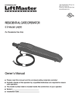
RESIDENTIAL GATE OPERATOR Model LA100 For Residential Use Only The Chamberlain Group, Inc. 845 Larch Avenue Elmhurst, Illinois 60126-1196 www.liftmaster.com Owner's Manual ■ Please read this manual and the enclosed safety materials carefully! ■ Periodic checks of the operator by a qualified - LiftMaster LA100 | LA100 Linear Gate Operator Manual - Page 2
27 Manual Release 27 Maintenance 28 Troubleshooting 29-30 REPAIR PARTS 29 Control Box 29 Gate Operator 30 ACCESSORIES 31 WARRANTY BACK TEMPLATE FOR POST BRACKET MOUNTING INTRODUCTION Safety Symbol and Signal Word Review This gate operator has been designed and tested to offer safe service - LiftMaster LA100 | LA100 Linear Gate Operator Manual - Page 3
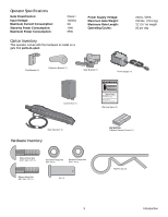
: Maximum Power Consumption: Class I 120Vac 2A 10W 55W Carton Inventory This operator comes with the hardware to install on a gate that pulls-to-open. Power Supply Voltage: Maximum Gate Weight: Maximum Gate Length: Operating Cycles: 24Vac, 50VA 250 lbs. (113.4 kg) 12' (3.7 m) length 20 per - LiftMaster LA100 | LA100 Linear Gate Operator Manual - Page 4
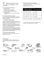
to attach a vertical support panel connecting the top rail to the bottom rail. The gate bracket can then be of UL listed, outdoor, infrared safety sensors. • LiftMaster Model 50-220 See page 25 for more information. installation and adjustment of the operator, instructions will call for tools as - LiftMaster LA100 | LA100 Linear Gate Operator Manual - Page 5
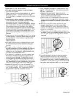
Safety Installation Information 1. READ and FOLLOW all instructions. 2. The gate operator is intended for use with Class I vehicular swing gates. Class I denotes a vehicular gate operator (or system) intended for use in a home of one to four single family dwellings, or a garage or parking area - LiftMaster LA100 | LA100 Linear Gate Operator Manual - Page 6
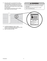
underground utility locating companies BEFORE digging. 14. SAVE THE INSTRUCTIONS. Moving Gate Can Cause Injury or Death KEEP CLEAR! Gate may move at any time without prior warning. Do not let children operate the gate or play in the gate area. This entrance is for vehicles only. Pedestrians must - LiftMaster LA100 | LA100 Linear Gate Operator Manual - Page 7
Property RIGHT HAND SWING tpTiPKDlheoEaimdyMsEeneiPoeosntwtnirCvltttiriLehhIataeEonnnncsuAgjctghaiRelt!umpiedrrusirGGsaoefyatrratnoeteruaowos.vearpemereashnriiyCeaDcntlpaegemea.rtsonaavhttoeeenChlagetyaanttauernasyonrece Warning Sign Hinge Post Bracket Gate Bracket Gate Operator Control Box PVC - LiftMaster LA100 | LA100 Linear Gate Operator Manual - Page 8
Check Your Gate Gate MUST be level. Gate and gate post MUST be plumb. Remove ANY/ALL wheels from the bottom of gate. Gate MUST NOT hit or drag across ground. Preparation and Overview 8 - LiftMaster LA100 | LA100 Linear Gate Operator Manual - Page 9
on type and style of your gate. NOTES: • The bottom of operator must be mounted at least 4" (10 cm) up from ground. Environmental conditions should be considered at this time. • Not recommended for plastic or vinyl gates. Refer to gate manufacturer for recommendation and options. Recommended - LiftMaster LA100 | LA100 Linear Gate Operator Manual - Page 10
and within 1' (.3 m) of the gate post. Do not mount control box more than 5' (1.5 m) from gate operator. PVC conduit (not provided) is Square Gate Post Screw (not provided) Q7 Figure 1 LEARN / CLOSE MODE / OPEN ALARM RESET JU1 R17 S1 D16 C42 S2 MIN R6 C38 C98 GATE FORCE instructed - LiftMaster LA100 | LA100 Linear Gate Operator Manual - Page 11
marked COM and 24Vac on the power supply provided. Refer to 'Wire Table' for recommended wire size and distance from the power supply and the gate operator control box (Figure 2). • Pull wire through one of the water tight connector nuts located on the bottom of the control box. Tighten nut firmly - LiftMaster LA100 | LA100 Linear Gate Operator Manual - Page 12
1 Attach Operator to Gate IDENTIFY HINGE TYPE The illustrations below show common gate hinges. There are many styles of hinges available. J-BOLT HINGE TOP VIEW Gate Post J-Bolt Hinge Point BUTT HINGE BARREL HINGE Installation Gate Post J-Bolt Hinge Point Gate Post Butt Hinge Point Gate Post - LiftMaster LA100 | LA100 Linear Gate Operator Manual - Page 13
of the post brackets: • Paper template (to be cut out) located on the back page of this manual. • Tape measure. Either method will work depending on preference. NOTE: Be sure gate is in closed position before proceeding. Template Method Place the template (provided on the back page) under the - LiftMaster LA100 | LA100 Linear Gate Operator Manual - Page 14
serrated flange nut. DO NOT TIGHTEN AT THIS TIME. Left-Hand Gate Right-Hand Gate 3/8" Ribbed Neck Bolt 3/8" Ribbed Neck Bolt Post Bracket Post Bracket An extension bracket is not necessary if the operator is being installed on a 6" (15 cm) or larger post. Installation 5/16" Serrated Flange - LiftMaster LA100 | LA100 Linear Gate Operator Manual - Page 15
post. Refer to the illustrations on page 9 for the ideal mounting options. With gate in closed position, place operator against gate post at the desired vertical position. • The bottom of the operator must be at least 4" (10 cm) off the ground. • Temporarily secure the post bracket to the post and - LiftMaster LA100 | LA100 Linear Gate Operator Manual - Page 16
DRILLING Ensure gate operator is level by placing level under the gate operator. Remove gate operator from brackets gate bracket can be secured to the gate using a welder. NOTE: Some installations may require reinforcement of existing gate structures for suitable support. Reinforcement Area Gate - LiftMaster LA100 | LA100 Linear Gate Operator Manual - Page 17
securing with the hairpin clips. Once you have verified that the operator is level and the 1/4" gap between the operator and the extension bracket has been maintained, tighten all of the post and gate bracket supporting hardware. IMPORTANT NOTE: When tightening the ribbed neck bolts that hold the - LiftMaster LA100 | LA100 Linear Gate Operator Manual - Page 18
.oasrtahvottCeeehnaglaeytanutaternsayonerce control wiring MUST be run in separate Connect Gate Operator to Control Box 1 WATERTIGHT CONNECTOR NUT Remove watertight connector nut from the control box. Insert operator cable through watertight connector nut. Watertight Connector Seal Nut - LiftMaster LA100 | LA100 Linear Gate Operator Manual - Page 19
Connector 24VAC Control Box Operator Cable Control Box Operator Cable PDpTKtiMlhmeEoadiEyseneoPoieswntntvCirtttliLiherhaIanEteonnncAusggjchtRaumeiptl!GdeirursGriysaoeaaftrrontetueorwaoesmv.rapeereaChsnDryeiiacnaptmelgeean.oasrtahvottCeeehnaglaeytanutaternsayonerce Operator 4 PLUG IN POWER - LiftMaster LA100 | LA100 Linear Gate Operator Manual - Page 20
Wiring Diagram To protect against fire and electrocution: • DISCONNECT power BEFORE installing or servicing operator. Q7 C38 C98 D16 C42 S2 K2 LEARN / CLOSE MODE / OPEN MIN R17 S1 RESET JU1 R6 GATE FORCE U2 U2 127A0154P6 2007 36 MAX +_ _+ IR SWITCH BLU RED WHT BRN GRN YEL 24VAC - LiftMaster LA100 | LA100 Linear Gate Operator Manual - Page 21
3-button remote control is pre-programmed to activate your gate operator. It is required to program your travel limits. • The YELLOW LED provides learning mode feedback. PROGRAMMING GATE TRAVEL (LIMIT LEARN) 1 SETTING THE OPEN POSITION • With the gate in the closed position, press and hold the BLACK - LiftMaster LA100 | LA100 Linear Gate Operator Manual - Page 22
reverse system and may cause damage to the gate or operator. The gate operator will automatically detect how much force is required to open and close the gate under normal conditions, however, the user must initialize the Gate Force Sensitivity. The Gate Force must be carefully adjusted to allow the - LiftMaster LA100 | LA100 Linear Gate Operator Manual - Page 23
or replacing the battery. THERE ARE NO OTHER USER SERVICEABLE PARTS. Tested to Comply with FCC Standards FOR HOME OR OFFICE USE. Operation is beep from the alarm that indicates programming has exited. NOTE: If the gate is open and the power is interrupted, the TTC will be disabled. Upon another - LiftMaster LA100 | LA100 Linear Gate Operator Manual - Page 24
operator can have a maximum of two pairs of safety sensors installed. The sensors come with two feet of wire leads. Additional 16AWG wire will be required (not provided). A typical installation should have safety sensors installed across the opening of the gate to detect the presence of a car and - LiftMaster LA100 | LA100 Linear Gate Operator Manual - Page 25
). To order call: 1-800-528-2806 or visit our website www.liftmaster.com. When properly connected and aligned, the sensor will detect an obstacle the path of its electronic beam and not allow the gate to move or stop the gate when moving. Entrapment Zone Safety Sensor Placement ENTRAPMENT ZONE: - LiftMaster LA100 | LA100 Linear Gate Operator Manual - Page 26
the owner's 3. ALWAYS keep people and objects away from the gate. NO manual. Have a qualified service person make repairs to ONE SHOULD CROSS THE PATH OF THE MOVING GATE. gate hardware. 4. Test the gate operator monthly. The gate MUST reverse 7. The entrance is for vehicles ONLY. Pedestrians - LiftMaster LA100 | LA100 Linear Gate Operator Manual - Page 27
Manual Release In case of a power failure, the operator can be disengaged from the gate. Follow the directions below to disconnect and reconnect the operator to the gate. RELEASE 1. Remove the hairpin clip. Turn release handle 180 degrees. 2. Swing operator up and away from gate and out of the way - LiftMaster LA100 | LA100 Linear Gate Operator Manual - Page 28
. Normal gate force Check for obstructions or excessive gate resistance. Relearn gate was exceeded. force (press PURPLE BUTTON 2 times then cycle gate). Force reversal while opening. Normal gate force was exceeded. Power on reset Control board issue. Replace control board. Operation and - LiftMaster LA100 | LA100 Linear Gate Operator Manual - Page 29
QTY 1 K-LA-8 Gate Operator 1 3 2 41ASWG-0014SA Rear Connector 1 3 KSWG-0580SA Hardware Kit 1 Includes: Gate Bracket, Post Bracket, Extension Bracket and Hardware Bag) Not Shown 41ASWG-1085SA Ribbed Neck Bolt 4 01-34410 Owner's Manual 1 29 Bracket Hardware Repair Parts - LiftMaster LA100 | LA100 Linear Gate Operator Manual - Page 30
clip. 377LM OPEN 50-220 OPEN WGB315 PRESS TO R ING The Protector System® Safety Sensors: The safety reversing sensors, are intended for installation with the operators covered in this manual. To order call: 1-800-528-2806 or visit our website www.liftmaster.com. 370LM Wireless Gate Doorbell - LiftMaster LA100 | LA100 Linear Gate Operator Manual - Page 31
AMERICA FOR INSTALLATION AND SERVICE INFORMATION, CALL OUR TOLL FREE NUMBER 1-800-528-2806 www.liftmaster.com WHEN ORDERING REPAIR PARTS PLEASE SUPPLY THE FOLLOWING INFORMATION: PART NUMBER DESCRIPTION MODEL NUMBER ADDRESS ORDER TO: THE CHAMBERLAIN GROUP, INC. Technical Support Group 6050 S. Country - LiftMaster LA100 | LA100 Linear Gate Operator Manual - Page 32
TEMPLATE FOR POST BRACKET MOUNTING 1 2 3 4 5 4 3 2 1 5 Shown actual size. 01-34410 © 2008, The Chamberlain Group, Inc. All Rights Reserved
-
 1
1 -
 2
2 -
 3
3 -
 4
4 -
 5
5 -
 6
6 -
 7
7 -
8
-
9
-
10
-
11
-
12
-
13
-
14
-
15
-
16
-
17
-
18
-
19
-
20
-
21
-
22
-
23
-
24
-
25
-
26
-
27
-
28
-
29
-
30
-
31
-
32
 |
 |

Owner’s Manual
■
Please read this manual and the enclosed safety materials carefully!
■
Periodic checks of the operator by a qualified technician are required to ensure
safe operation.
■
The model number label is located inside the control box of your operator.
■
Serial #
■
Installation Date
RESIDENTIAL GATE OPERATOR
Model LA100
For Residential Use Only
The Chamberlain Group, Inc.
845 Larch Avenue
Elmhurst, Illinois 60126-1196
www.liftmaster.com