LiftMaster LA400 LA400 Manual - Page 22
Important Note - accessories
 |
UPC - 753182403953
View all LiftMaster LA400 manuals
Add to My Manuals
Save this manual to your list of manuals |
Page 22 highlights
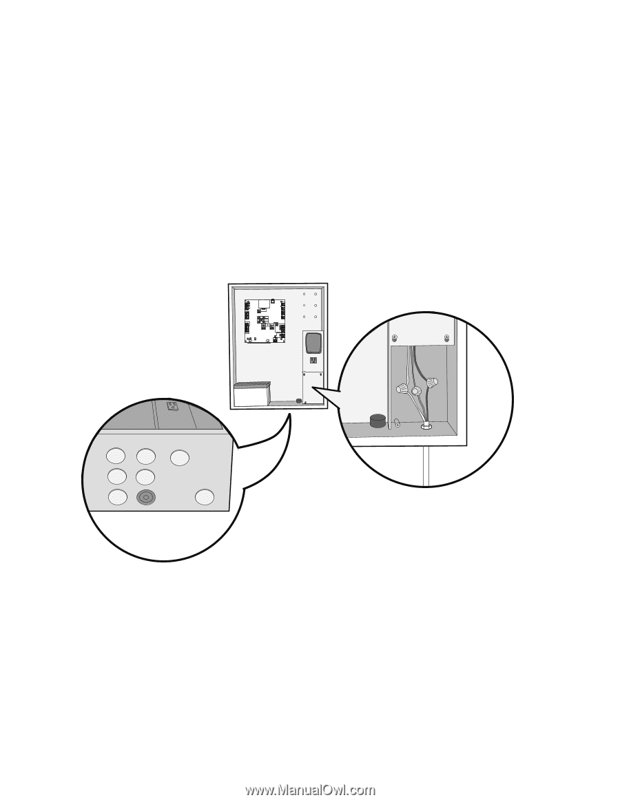
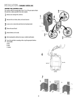
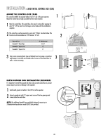
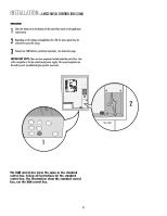
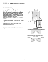
INSTALLATION » LARGE METAL CONTROL BOX (XLM) WIRING 1 Select the knock out in the bottom of the control box based on the application requirements. 2 Depending on the voltage and application the 120 Vac access panel may be removed to access the wiring. 3 Connect two 7AH batteries, purchased separately. See Accessories page. IMPORTANT NOTE: There are two receptacles located inside the control box. One of the receptacles is for the control board power supply. The second receptacle can be used to power up additional gate operator accessories. ALARM LOCK SOL GND MAGR GATE 1 BR GR WH YL BL RD ACCESSORY POWER 12 V BR GR WH YL BL RD GATE 2 LEARN XMITTER ON OFF LOCK / BIPA RT DELAY CLOSE EDGE OPEN EDGE/ PHOTO OPEN PHOTO SET OPEN LIMIT GATE 1 CLOSE PHOTO SET CLOSE LIMIT LEARN LIMITS FORCE GATE 2 ON OFF AUTO OPEN LOW BATT OFF MAX SINGLE BUTTON TIMER TO CLOSE OPEN CONTROL INPUTS SINGLE BUTTON RESET OFF MAX STOP CTRL PWR CTRL PWR SHADOW LOOP INPUTS INTERRUPT CHGR OVLD CTRL PWR AC PWR /SOLAR 1 2 120 Vac ONLY The XLM control box wires the same as the standard control box. Follow all instructions for the standard control box. The illustrations show the standard control box, not the XLM control box. 21
-
 1
1 -
2
-
3
-
4
-
5
-
6
-
7
-
8
-
9
-
10
-
11
-
12
-
13
-
14
-
15
-
16
-
 17
17 -
 18
18 -
 19
19 -
 20
20 -
 21
21 -
 22
22 -
 23
23 -
 24
24 -
 25
25 -
 26
26 -
 27
27 -
28
-
29
-
30
-
31
-
32
-
33
-
34
-
35
-
36
-
37
-
38
-
39
-
40
-
41
-
42
-
43
-
44
-
45
-
46
-
47
-
48
 |
 |