LiftMaster LA400 LA400 Manual - Page 23
Wiring
 |
UPC - 753182403953
View all LiftMaster LA400 manuals
Add to My Manuals
Save this manual to your list of manuals |
Page 23 highlights
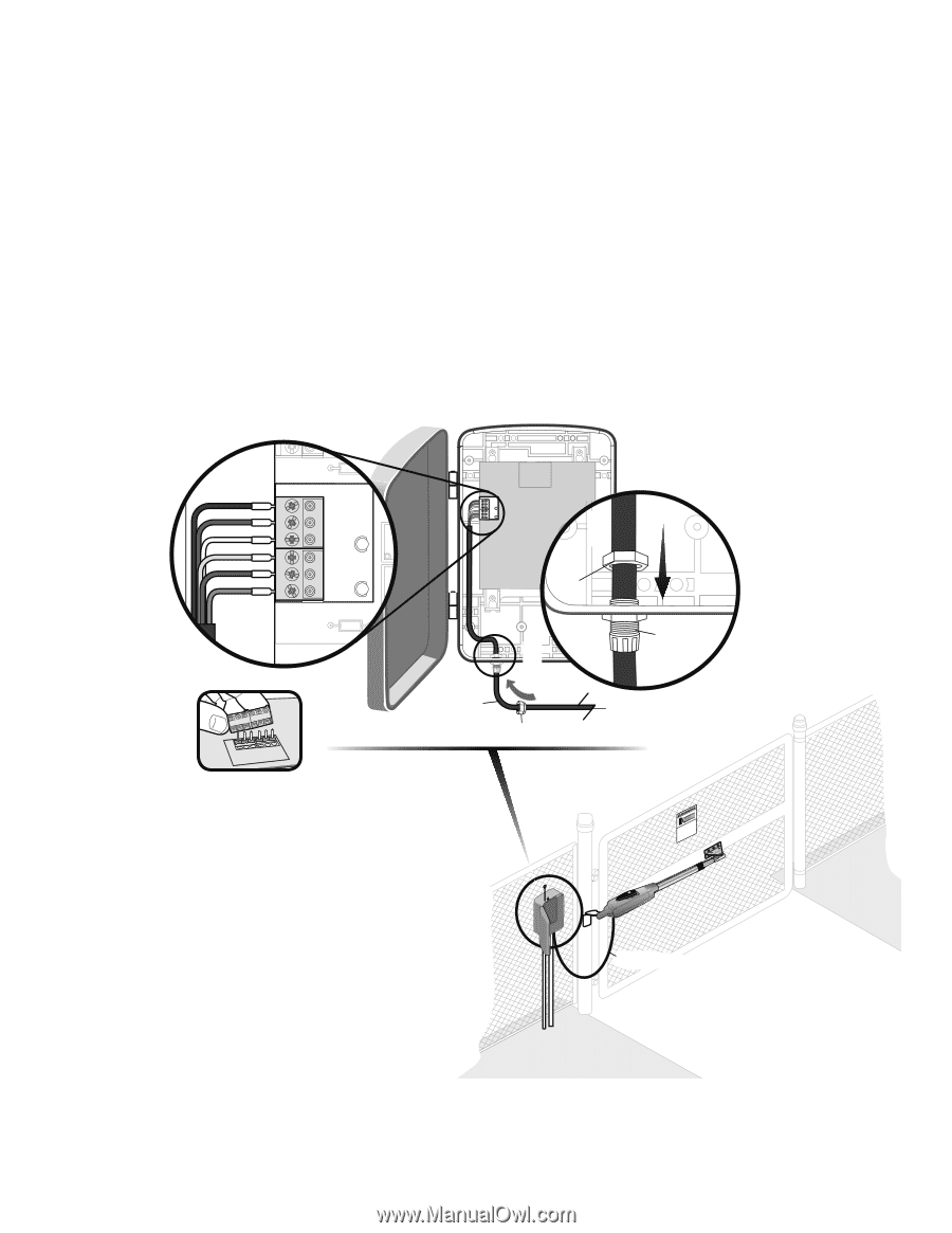
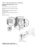
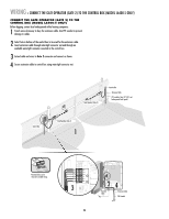
WIRING » CONNECT THE GATE OPERATOR (GATE 1) TO THE CONTROL BOX CONNECT THE GATE OPERATOR (GATE 1) TO THE CONTROL BOX 1 Select hole in bottom of the control box to be used for the operator cable. 2 Insert the watertight connector into the bottom of the control box and tighten with nut. 3 Insert the operator cable through the watertight connector mounted in the bottom of the control box. 4 Extend the operator cable and wires to the Gate 1 connector and connect as shown. 5 Tighten watertight connector nut. NC 4 Z1 GATE 1 10A 32V BRN D1Ø GRN WHT YEL BLU RED Z12 ACCESSORY POWER GATE 1 BRN GRN WHT U4 YEL BLU RED 3 MAX C13 C4 F6 F2 FUSE OPEN Nut 52 Operator Cable 1 Watertight Connector Nut Terminal blocks can be removed to simplify wiring. Watertight Connector KtDpTPiMmlheEoaidEyseneoPoieswntnvtCirtttliLiehhrIaanEteonnncAusggjchtRauemiplt!GdeirursGriysoaeaaftrrnoteteuorwaoesmv.rapeereaChnsDryeiiacnapmtelgeean.oasrtahvottCeeehnaglaeytanuattenrsayonerce Operator Cable If installing one operator, proceed to page 27. If installing two operators, continue to the next page. 22
-
 1
1 -
2
-
3
-
4
-
5
-
6
-
7
-
8
-
9
-
10
-
11
-
12
-
13
-
14
-
15
-
16
-
17
-
 18
18 -
 19
19 -
 20
20 -
 21
21 -
 22
22 -
 23
23 -
 24
24 -
 25
25 -
 26
26 -
 27
27 -
 28
28 -
29
-
30
-
31
-
32
-
33
-
34
-
35
-
36
-
37
-
38
-
39
-
40
-
41
-
42
-
43
-
44
-
45
-
46
-
47
-
48
 |
 |