LiftMaster LA400 LA400 Manual - Page 44
» Troubleshooting Chart - - replacement control board
 |
UPC - 753182403953
View all LiftMaster LA400 manuals
Add to My Manuals
Save this manual to your list of manuals |
Page 44 highlights
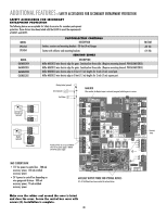
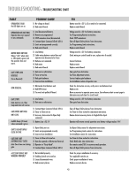
TROUBLESHOOTING » TROUBLESHOOTING CHART FAULT OPERATOR IS DEAD No LED lights are on. OPERATOR DOES NOT RUN Operator does not respond to any commands. MOTOR DOES NOT RUN Relays "click" when radio or SBC signal is given, but the operator does not move. GATE STOPS AND REVERSES (Force Reversal) RPM REVERSAL POSSIBLE CAUSE 1) No voltage to board. 2) Bad control board. 1) Low/disconnected battery. 2) Remote not programmed. 3) STOP connection loose/disconnected. 4) Constant Open Command (Check LED's). 5) Limits not programmed correctly. 6) Bad control board. 1) Low Battery. 2) Cable wiring between control box and operator arm disconnected or loose. 3) Batteries not connected. 4) Bad motor. 5) Bad control board. 1) Gate met an obstruction. 2) Force set too low. 3) Bad gate hardware. 4) Incorrect Arm installation. 1) Obstructed Arm (bottoms out). 2) Bad RPM Sensor. 3) Too much mA pulled off board. GATE STOPS Gate starts to run, then stops and does not reverse. GATE OPENS BUT DOES NOT CLOSE Audible beeps (3 times) when command is given. GATE'S DO NOT OPEN/ CLOSE IN SYNC GATE DOES NOT AUTOMATICALLY CLOSE Auto Close Timer not closing gate. 1) Low battery. 2) Gate met an obstruction. 1) Constant Open Command (Check LED's). 2) Timer-to-Close not set. 3) Accessory device wired to Open Only command. 1) Battery Low >23.5 V 1) Bipart Delay not set. 2) Limits not programmed correctly. 3) Incorrect Arm Installation 1) Timer-to-Close not turned on. 2) Gate has opened on Obstruction Reversal. 3) Operator in "Party Mode". 4) Constant Open Command (Check LED's). ACCESSORY DEVICE NOT WORKING PROPERLY 1) Not installed properly. 2) Enabling Switch not turned on. 3) Loose/disconnected wires. 4) Bad accessory device FIX Battery must be >23 V, AC or needs to be connected. Replace control board. Voltage must be >23 V at battery connection. See Programming Remote instructions. Check STOP connections. Clear all Open/Safety devices from obstruction. See Programming Limits instructions. Replace control board. Voltage must be >23 V at battery connection. Check wiring on control board to arm, replace wire if needed. Connect batteries. Replace motor. Replace control board. Clear gate from obstruction. See Force Adjustment section. Service/replace gate hardware. See Installation section of operator arm. Check for obstruction on arm, verify arm is not bottomed out. Replace arm. Move accessories to separate power source. Use reference chart on next page to determine max mA draw for circuit board. Voltage must be >23 V at battery connection. Clear gate from obstruction. Clear all Open/Safety devices from obstruction. See Timer-to-Close section for adjustment instructions. Rewire desired accessory device to Single Button Input. Operator will resume normal operation once battery voltage reaches 24 V. See Bipart Delay section for adjustment instructions. See Programming Limits section for instructions. See Installation section for instructions. See Timer-to-Close section for instructions. Check DIAG code, clear obstruction. Use remote control/SBC to resume normal operation. Clear all Open/Safety devices from obstruction. Check for proper installation of accessory. Turn applicable switches on. Check proper installation of wires. Replace accessory device. 43
-
 1
1 -
2
-
3
-
4
-
5
-
6
-
7
-
8
-
9
-
10
-
11
-
12
-
13
-
14
-
15
-
16
-
17
-
18
-
19
-
20
-
21
-
22
-
23
-
24
-
25
-
26
-
27
-
28
-
29
-
30
-
31
-
32
-
33
-
34
-
35
-
36
-
37
-
38
-
 39
39 -
 40
40 -
 41
41 -
 42
42 -
 43
43 -
 44
44 -
 45
45 -
 46
46 -
 47
47 -
 48
48
 |
 |