LiftMaster MJ MJ5011E Installation-2008 Manual
LiftMaster MJ Manual
 |
View all LiftMaster MJ manuals
Add to My Manuals
Save this manual to your list of manuals |
LiftMaster MJ manual content summary:
- LiftMaster MJ | MJ5011E Installation-2008 Manual - Page 1
INSTALLATION MANUAL MODEL MJ5011E • MH5011E • MHS5011E MEDIUM DUTY DOOR OPERATOR RaNdoBiwuoiRlwteiitcnheiver INTENDED FOR PROFESSIONAL INSTALLATION ONLY Visit www.LiftMaster.com to locate a professional installing dealer in your area. 2 YEAR WARRANTY Serial # (located on electrical box cover) - LiftMaster MJ | MJ5011E Installation-2008 Manual - Page 2
IMPORTANT NOTES: • BEFORE attempting to install, operate or maintain the operator, you must read and fully understand this manual and follow all WWAARRNNININGG safety instructions. • DO NOT attempt installation, repair or service of your commercial door and gate operator unless you are an Authorized - LiftMaster MJ | MJ5011E Installation-2008 Manual - Page 3
APPLICATIONS INTRODUCTION This Medium Duty Commercial Door Operator includes a number of features that will provide years of reliable and safe operation. Features: • Supports both monitored and non-monitored safety devices: Safety devices detect obstructions in the door's path and automatically - LiftMaster MJ | MJ5011E Installation-2008 Manual - Page 4
DISCONNECT: MH Floor level chain hoist for emergency manual chain hoist operation. MJ Floor level disconnect for emergency manual operation. MHS Both disconnects described above. ENTRAPMENT PROTECTION: . . . . . Supports both monitored and non-monitored safety devices including LiftMaster CPS - LiftMaster MJ | MJ5011E Installation-2008 Manual - Page 5
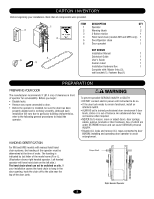
. 3 ^OPEN ^CLOSE O STOP 1 2 ITEM 1 2 3 4 5 6 DESCRIPTION QTY Operator 1 Warning labels 2 3-Button station 1 Hoist hand chain (models MH and MHS only) 1 Door/Operator chain 1 Door sprocket 1 4 6 5 NOT SHOWN Installation Manual 1 Quickstart Guide 1 User's Guide 1 Caution - LiftMaster MJ | MJ5011E Installation-2008 Manual - Page 6
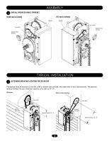
(not provided, see accessories or door manufacturer). The optimum distance between the door shaft and operator drive shaft is 12"-15". Wall mount Shelf or bracket mounting Door Shaft Door Shaft Operator Drive Shaft Optimum Distance 12 - 15" Operator Drive Shaft Optimum Distance 12 - 15 - LiftMaster MJ | MJ5011E Installation-2008 Manual - Page 7
DOOR SPROCKET ON DOOR SHAFT 3 PLACE OPERATOR DOOR SPROCKET ON OPERATOR Door Shaft Operator Door Sprocket Drive Shaft Operator Drive Sprocket 4 WRAP DRIVE CHAIN AROUND DOOR SPROCKET 5 WRAP DRIVE CHAIN AROUND OPERATOR SPROCKET Drive Chain Door Sprocket Electrical Box Door Sprocket Operator - LiftMaster MJ | MJ5011E Installation-2008 Manual - Page 8
Key Secure both sprockets with key and set screw. If sprockets are not secure, they may drift and cause damage to operator. Operator Drive Sprocket Door Sprocket Keep door sprocket and operator door sprocket aligned. If sprockets are not aligned, they may cause premature wear on the chain. 8 - LiftMaster MJ | MJ5011E Installation-2008 Manual - Page 9
door from the door operator and a disconnect chain with manual hoist to electrically disable the operator controls. A Secure chain retaining bracket to wall (MH AND MHS ONLY) Chain Retaining Bracket (with pad locking provisions) B Wrap hand chain around hand chain wheel and through chain guide (MH - LiftMaster MJ | MJ5011E Installation-2008 Manual - Page 10
and secured, at that time the unit may be returned to service. • Disconnect power at the fuse box BEFORE proceeding. Operator MUST be properly grounded and connected in accordance with local electrical codes. The operator should be on a separate fused line of adequate capacity. • ALL electrical - LiftMaster MJ | MJ5011E Installation-2008 Manual - Page 11
the door. • Or ANY other control (automatic or manual) is used. Reversing devices are recommended for ALL installations. Select appropriate knockout and run wire according to local electrical code from operator to 3-button control station. AVERTISSEMENOTperator Conduit ATTENTION ^OPEN CLOSE - LiftMaster MJ | MJ5011E Installation-2008 Manual - Page 12
INSTALLATION 13 SETUP RADIO ANTENNA Option A Locate the wire antenna on the outside of the electrical box. Cut the wire tie closest to the edge of the electrical box. Option B Locate the wire antenna on the outside of the electrical box. Cut wire ties and discard standoff. Cut this Wire Tie Press - LiftMaster MJ | MJ5011E Installation-2008 Manual - Page 13
OPEN limit Retaining Plate OPEN Limit Nut OPEN Limit Switch CLOSE Limit Nut AVERTISSEMENCLTOSE Limit Switch ATTENTION Increase Door Travel Adjust CLOSE limit Increase Door Travel Decrease Door Travel AVERTISSEMENT AVERTISSEMENT Decrease Door tension to permit smooth operation. • Secure clutch nut - LiftMaster MJ | MJ5011E Installation-2008 Manual - Page 14
its invisible light beam. If an obstruction breaks the light beam while the door is closing, the door will stop and typically reverse to the full open position. The photo eyes must be installed facing each other across the door, no more than 6" (15 cm) above the floor. SENSING EDGES When properly - LiftMaster MJ | MJ5011E Installation-2008 Manual - Page 15
ANT X ANT TTC ^^^^ 1 LEARN STOP CLOSE OPEN LEDD14 2 3 45 LMEP1 LMEP2 COM INTRLK STOP CLOSE OPEN 67 OPTIONAL SAFETY DEVICE CONFIGURATIONS CPS Photo-Eyes (White) (White/Black) NOTE: When installing model CPS-LN4, connect the brown wire to terminal 1 and the blue wire to terminal 2. CPS - LiftMaster MJ | MJ5011E Installation-2008 Manual - Page 16
Button Purple Wire Antenna Auxiliary Antenna Connection LED Field Wiring Terminal Factory Wiring Connector FUNCTION Open Door Close Door Stop Door Programs the remote controls and performs additional programming Programs the Timer to Close Primary Antenna For use with external antenna kit EXT-ANT - LiftMaster MJ | MJ5011E Installation-2008 Manual - Page 17
of the door. • Or ANY other control (automatic or manual) is Disconnect then reconnect power to the operator. Press and hold the LEARN OPEN LED 2 3 4 5 6 7 K2 LT C29 R24 P1 D9 LMEP1 LMEP2 COM INTRLK STOP CLOSE OPEN LEARN STOP CLOSE OPEN LEDD14 1 2 3 4 5 6 7 Photo Eye TO PROGRAM - LiftMaster MJ | MJ5011E Installation-2008 Manual - Page 18
BASIC PROGRAMMING B2 WIRING TYPE WITHOUT MONITORED SAFETY DEVICE C Requires a non-monitored safety device. • Momentary contact to open, close and stop. • Open override that reverses when closing by any opening device. • Wiring for safety device to reverse. NOTE: The operator will automatically - LiftMaster MJ | MJ5011E Installation-2008 Manual - Page 19
ARE NO OTHER USER SERVICEABLE PARTS. Tested to Comply with FCC Standards FOR HOME OR OFFICE USE. Operation is subject to the operator to close from the open limit after a preset time, adjustable from 5 to 60 seconds. Requires LiftMaster monitored safety device. TO PROGRAM 1. Begin with door - LiftMaster MJ | MJ5011E Installation-2008 Manual - Page 20
B2 wiring type and compatible LiftMaster remote control. In C2 wiring the remote control will open the door only. 1. Press remote control button. 2. Door should open. Allow the door to fully open. 3. Press remote control button. 4. Door should close. Allow door to fully close. ADVERTENCIA PRECAUCI - LiftMaster MJ | MJ5011E Installation-2008 Manual - Page 21
the door from the door operator and a disconnect chain with manual hoist to electrically disable the operator controls. 1. Refer to Model MH instructions for hoist operation. 2. Refer to Model MJ instructions for manual operation. When operator is disconnected by the manual operation chain, hoist - LiftMaster MJ | MJ5011E Installation-2008 Manual - Page 22
Close and Open the door. TTC will be re-enabled. C) TTC not programmed properly ➤ Reprogram TTC. See PROGRAMMING TTC section. RADIO FUNCTIONALITY NOTE: Built in radio receiver compatible with all LiftMaster 315MHz remote control devices. NO RESPONSE REMOTE CANNOT BE LEARNED A) Remote control is - LiftMaster MJ | MJ5011E Installation-2008 Manual - Page 23
wires on the capacitor. Check clutch adjustment. Door height or speed may exceed the range the operator can travel. Call Technical Support for assistance. Replace Logic Board. NOTE: Purple Yellow Grey Safety Limit Switch Open Limit Switch Grey Close Limit Switch 23 AANTUX ANT J2 TTC LEARN - LiftMaster MJ | MJ5011E Installation-2008 Manual - Page 24
4 K3 K4 K2 2 K1 1 K5 3 SERVICE KITS ITEM PART # DESCRIPTION K1 K72-33872-1 Medium Duty "E", 315 MHz K4 K001A6424-3 Logic Board, Medium Duty "E", 390 MHz K5 K74-31243 MOV and terminal block * To order complete electrical box kit, add a (K-) prefix to the model number for the operator - LiftMaster MJ | MJ5011E Installation-2008 Manual - Page 25
REPAIR PARTS KITS - MH K7 K8 1 K2 K6 K1 K4 K6 K4 SERVICE KITS ITEM K1 K2 K3 K4 K6 K7 K8 lock washers, and cotterpins Motor, 1/2 hp, 115 Volt. Clutch shaft kit Complete with: Disc, chain guide, release holder, 4L V-Belt, 4L motor pulley, 7" O.D., shaft, wheel, washers, bushings, bearings, nuts - LiftMaster MJ | MJ5011E Installation-2008 Manual - Page 26
1 K3 K2 K3 K6 K1 K8 K4 K6 2 K4 K3 SERVICE KITS ITEM K1 K2 K3 K4 K6 K7 K8 PART # K75-33877 Frame spacer kit Complete with: Spacer, nuts and bolts Electrical box Disconnect assembly Complete with: Support bracket, yoke, level, shaft, spring, sash, chain, screws, nuts, cotterpins and roll - LiftMaster MJ | MJ5011E Installation-2008 Manual - Page 27
REPAIR PARTS KITS - MHS K5 K6 K4 K2 K1 1 K3 K4 2 K3 K3 K2 SERVICE KITS ITEM K1 K2 K3 K4 K5 K6 PART # K20-5150-LD-1 K72-33841 K72-33962 K75-10030 K75-33948 DESCRIPTION Motor, 1/2 hp, 115 Volt. Clutch shaft kit Complete with: Disc, chain guide, release holder, 4L V-Belt, 4L motor - LiftMaster MJ | MJ5011E Installation-2008 Manual - Page 28
OPERATOR NOTES 28 - LiftMaster MJ | MJ5011E Installation-2008 Manual - Page 29
OPERATOR NOTES 29 - LiftMaster MJ | MJ5011E Installation-2008 Manual - Page 30
OPERATOR NOTES 30 - LiftMaster MJ | MJ5011E Installation-2008 Manual - Page 31
brPaREcSSket, Painted steel, for TO MJ, MH, and MHS.RING 10-9095 ANTENNA EXT-ANT OPEN Medium Duty Angle Mounting Bracket: CLOSE Heavy-gauge steel bracket. May be welded. For use with MJ, MGJ, and MH operators. OPEN CLOSE Antenna: External kit for medium duty. PRESS TO R ING 86LM (15') 86LMT - LiftMaster MJ | MJ5011E Installation-2008 Manual - Page 32
with the Commercial Door Operator. 3 BUTTON STATION OR 3 POSITION KEYSWITCH WITH SPRING RETURN TO CENTER AND STOP BUTTON STANDARD 2 OR MORE KEY LOCKOUT 7635 7635 7635 Open Close Stop Open Close Stop Open Close Stop Open Close Stop Keyswitch 2 BUTTON STATION OR 3 POSITION KEYSWITCH
-
 1
1 -
 2
2 -
 3
3 -
 4
4 -
 5
5 -
 6
6 -
 7
7 -
8
-
9
-
10
-
11
-
12
-
13
-
14
-
15
-
16
-
17
-
18
-
19
-
20
-
21
-
22
-
23
-
24
-
25
-
26
-
27
-
28
-
29
-
30
-
31
-
32
 |
 |

Serial #
(located on electrical box cover)
Installation Date
2
YEAR
WARRANTY
NOT FOR RESIDENTIAL USE
I N S T A L L A T I O N
M A N U A L
MODEL
MJ5011E • MH5011E • MHS5011E
MEDIUM DUTY DOOR OPERATOR
Now with
Built in
Radio Receiver
Radio Receiver
Built on Board
315MHz
INTENDED FOR PROFESSIONAL
INTENDED FOR PROFESSIONAL
INSTALLATION ONLY
INSTALLATION ONLY
Visit www.LiftMaster.com to locate a professional installing dealer in your area.
A SAFETY DEVICE IS HIGHLY RECOMMENDED.