LiftMaster MJ MJ (BLACK LINE) Manual
LiftMaster MJ Manual
 |
View all LiftMaster MJ manuals
Add to My Manuals
Save this manual to your list of manuals |
LiftMaster MJ manual content summary:
- LiftMaster MJ | MJ (BLACK LINE) Manual - Page 1
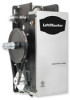
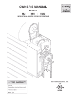
OWNER'S MANUAL MODELS: MJ ✦ MH ✦ HMJ INDUSTRIAL DUTY DOOR OPERATOR FACTORY SET C2 Wiring See page 8 for other wiring configurations 2 YEAR WARRANTY Serial # (located on electrical box cover) Installation Date Wiring Type NOT FOR RESIDENTIAL USE 41B6 - LiftMaster MJ | MJ (BLACK LINE) Manual - Page 2
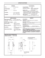
CHAIN WHEEL: .........Left or right handing Models MH and HMJ only. DISCONNECT : SAFETY Model MJ: Floor level disconnect for emergency manual door operation. Model MH: Floor level chain hoist with electrical interlock for emergency manual door operation. Model HMJ: Includes both floor level - LiftMaster MJ | MJ (BLACK LINE) Manual - Page 3
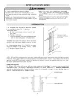
with manual hoist hand chain systems, the handing of the operator must be determined at the time of order. The handing is indicated by last letter of the model name (R or L). The hand chain wheel can not be switched on site. If your installation causes the hand chain to hang in the door opening - LiftMaster MJ | MJ (BLACK LINE) Manual - Page 4
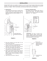
on page 3. Refer to the illustration and instructions below that suits your application. 1a. Wall Mounting The operator should generally be installed below the door shaft, and as close to the door as possible. The optimum distance between the door shaft and operator drive shaft is between 12" - 15 - LiftMaster MJ | MJ (BLACK LINE) Manual - Page 5
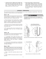
to disconnect the door from the door operator and a disconnect chain with manual hoist to electrically disable the operator controls. 1. Refer to Model MH instructions above for hoist operation. 2. Refer to Model MJ instructions above for manual operation. 5 Manual Disconnect for Models MJ and HMJ - LiftMaster MJ | MJ (BLACK LINE) Manual - Page 6
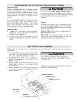
or Safety Edge. TAKE-UP REEL: Take-up reel should be installed 12" above the top of the door. COIL CORD: Connect operator end of coil cord to junction box (not supplied) fastened to the wall approximately halfway up the door opening. LIMIT SWITCH ADJUSTMENT WARNING WARNING NOTE: Make sure the limit - LiftMaster MJ | MJ (BLACK LINE) Manual - Page 7
to door and operator, make ALL door locks inoperative. Secure locks(s) in "OPEN" position. If the door lock needs to remain functional, install an , call the number on the back of this manual. DO NOT INSTALL ANY WIRING OR ATTEMPT TO RUN THIS OPERATOR WITHOUT CONSULTING THE WIRING DIAGRAM. 2. Be sure - LiftMaster MJ | MJ (BLACK LINE) Manual - Page 8
or manual) is used. Reversing devices are recommended for ALL installations. Constant pressure on close (C2 wiring) In the electrical enclosure, a RED wire was placed on terminal block #12. With this setting, the operator will require constant pressure on close control in order to keep door moving - LiftMaster MJ | MJ (BLACK LINE) Manual - Page 9
a commercial door opener, a reversing edge MUST be installed on the bottom of the door. Failure to install a reversing edge under these circumstances may result in SERIOUS INJURY or DEATH to persons trapped beneath the door. CAUTIWONARNING gate or garage door: • ALWAYS keep remote controls out - LiftMaster MJ | MJ (BLACK LINE) Manual - Page 10
for the the life of the friction pad. If desired, a brake can also be field installed. To order a kit for field installation on an existing operator, call the parts and service department at 1-800-528-2806. Replace friction pads when necessary. Refer to the illustration for identification - LiftMaster MJ | MJ (BLACK LINE) Manual - Page 11
SERVICE ORGANIZATION SPANS AMERICA Installation and service information is available CALL OUR TOLL FREE number: 1-800-528-2806 WHEN ORDERING REPAIR PARTS PLEASE SUPPLY THE FOLLOWING INFORMATION: PART NUMBER DESCRIPTION MODEL NUMBER ADDRESS ORDER TO: THE CHAMBERLAIN GROUP, INC. Technical Support - LiftMaster MJ | MJ (BLACK LINE) Manual - Page 12
AUX. EDGE 10 CLOSE L/S GY GY GY OR A.R.S. BOARD (When Present) 54 3 2 1 OR OP Y W PULL SWITCH TO OPEN & CLOSE 7 Y R2 Y AUX. OPEN L/S R CLOSE P P CL 2 * TO REVERSE MOTOR ROTATION INTERCHANGE RED AND YELLOW MOTOR WIRES. OPEN L.S. OR N.C. W 11 C W CLOSE L/S P W N.C. C 12 - LiftMaster MJ | MJ (BLACK LINE) Manual - Page 13
CL BL/BK PP BL R GY 5 R OR 4 OR P BR Y Y GY W BL BK BK 3 2 GROUND 1 1 2 3 4 7 10 11 12 L1 L2 A.R.S. BOARD (When Present) OPEN CLOSE STOP RATED LINE VOLTAGE PULL SWITCH TO OPEN & CLOSE SAFETY EDGE See Close Control Wiring Options Below * - Shipped from Factory CLOSE CONTROL WIRING - LiftMaster MJ | MJ (BLACK LINE) Manual - Page 14
ELECTRICAL BOX - ILLUSTRATED PARTS 2 L5 L8 L3 L8 L6 3 6 4 8 L2 S5 S3 L1 S4 L7 L3 S5 S3 S4 S8 S2 S7 S1 L2 S6 L6 L4 7 5 1 9 14 - LiftMaster MJ | MJ (BLACK LINE) Manual - Page 15
. Refer to page 11 for all repair part ordering information. Complete Electrical Box Service Kits K-MJ5011 Model MJ5011, 115V K-MJ5025 Model MJ5025, 230V K-MH5011R Model MH5011R, 115V RH K-MH5011L Model MH5011L, 115V LH K-MH5025R Model MH5025R, 230V RH K-MH5025L Model MH5025L, 230V LH - LiftMaster MJ | MJ (BLACK LINE) Manual - Page 16
ILLUSTRATED PARTS - Model MJ 16 C15 C4 C15 C5 B7 B4 O8 O3 O10 O5 O2 C3 C15 C13 C14 O7 C2 C9 O9 O1 3 D1 4 D4 1 D9 D2 D8 D7 D5 D6 D3 B12 B2 5 B3 B6 C4 1 2 B1 B11 B2 B8 B5 B10 B9 O2 C15 O12 O4 O10 O6 C1 C10 C6 C7 C8 C12 C11 - LiftMaster MJ | MJ (BLACK LINE) Manual - Page 17
Pin 1/8x1-3/4" ZP Cotter Pin 5/32x1-1/2" Roll Pin 1/8x1" K75-12588 · MH DISCONNECT SERVICE KIT ITEM H1 H2 H3 H4 H5 H6 PART# 10-10707 10-10708 10-10875 10-10988 11-10982 19-8A-12 DESCRIPTION Disconnect Support Bracket Yoke Disconnect Lever Interlock Switch Actuator Disconnect Shaft Sash Chain, 12 - LiftMaster MJ | MJ (BLACK LINE) Manual - Page 18
ILLUSTRATED PARTS - Model MH 18 C12 C14 C2 O8 O3 O10 C6 C7 C5 C3 O5 O2 C20 C5 O7 C8 C4 C17 C16 C18 O9 O1 3 4 D1 D4 1 B7 B12 B2 B4 5 1 C5 2 O2 C20 B1 B11 B2 B8 C1 C13 C9 C10 B3 B6 B5 B10 B9 D2 D5 D6 D3 O10 O4 O8 O6 C11 C19 C15 - LiftMaster MJ | MJ (BLACK LINE) Manual - Page 19
REPLACEMENT PARTS LIST - MODEL MH ITEM K1 K2 SERVICE KITS PART# K72-19979 K72-19974 DESCRIPTION Clutch Shaft Kit Complete with: Clutch Shaft, Keyed Flange Bearing, Dual Sprocket 32/14, 14 Tooth Sprocket, E-Ring, Compression Spring, Chain Wheel Assembly, Pulley Assembly, Chain Guide Assembly, - LiftMaster MJ | MJ (BLACK LINE) Manual - Page 20
ILLUSTRATED PARTS - Model HMJ 20 C14 C16 C3 C21 C6 C7 C8 C6 C4 C21 C9 O8 O3 O10 O5 O2 C5 O7 C21 C2 C19 C20 C13 - LiftMaster MJ | MJ (BLACK LINE) Manual - Page 21
REPLACEMENT PARTS LIST - MODEL HMJ ITEM K1 K2 SERVICE KITS PART# K72-19975 K72-19974 DESCRIPTION Clutch Shaft Kit Complete Key and Conduit. * Call for Pricing and Availablity ITEM 1 2 3 4 5 6 7 8 9 10 11 12 13 14 15 16 INDIVIDUAL PARTS PART# DESCRIPTION 11-19470* Clutch Shaft - J 12- - LiftMaster MJ | MJ (BLACK LINE) Manual - Page 22
OPERATOR NOTES 22 - LiftMaster MJ | MJ (BLACK LINE) Manual - Page 23
OPERATOR NOTES 23 - LiftMaster MJ | MJ (BLACK LINE) Manual - Page 24
be any normally open two wire device such as pullswitch, single button, loop detector, card key or such device. 4) When adding accessories, install them one at a time and test each one after it is added to ensure proper installation and operation with the Commercial Door Operator. 5) Use 16 gauge
-
 1
1 -
 2
2 -
 3
3 -
 4
4 -
 5
5 -
 6
6 -
 7
7 -
8
-
9
-
10
-
11
-
12
-
13
-
14
-
15
-
16
-
17
-
18
-
19
-
20
-
21
-
22
-
23
-
24
 |
 |

OWNER’S MANUAL
MODELS:
MJ
✦
MH
✦
HMJ
INDUSTRIAL DUTY DOOR OPERATOR
NOT FOR RESIDENTIAL USE
Serial #
(located on electrical box cover)
Installation Date
Wiring Type
2
YEAR
WARRANTY
C2 Wiring
FACTORY SET
See page 8 for
other wiring
configurations
41B6