LiftMaster MT MT5011E QuickStart Guide Manual
LiftMaster MT Manual
 |
View all LiftMaster MT manuals
Add to My Manuals
Save this manual to your list of manuals |
LiftMaster MT manual content summary:
- LiftMaster MT | MT5011E QuickStart Guide Manual - Page 1
QuickStart for the model MT/BMT door operator Medium Duty Logic This QuickStart is intended to highlight a typical installation. These instructions are not intended to be comprehensive. Because each application is unique, it is the responsibility of the purchaser, designer, installer and end user - LiftMaster MT | MT5011E QuickStart Guide Manual - Page 2
, it should generally be possible to stop the door by hand during travel. Reinstall cotter pin when finished. 13 Additional programming and troubleshooting can be found in the installation manual. 01-34216B © 2008, The Chamberlain Group, Inc. All Rights Reserved 7 L-Slot 4 L-Slo4t 4 Clutch
-
 1
1 -
 2
2
 |
 |

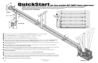
QuickStart
for the model MT/BMT door operator
Medium Duty Logic
This QuickStart is intended to highlight a typical installation. These instructions are not intended to be comprehensive. Because each application is unique, it is the
responsibility of the purchaser, designer, installer and end user to ensure that the total door system is safe for its intended use. Please consult the manual and/or a
qualified technician for further information.
NOTE: Intended for Professional Installation Only. Visit www.LiftMaster.com to locate a professional installing dealer in your area.
A SAFETY DEVICE IS HIGHLY RECOMMENDED
Timer to Close Programming
Programming Remote Controls
Timer to Close feature enables the operator to close the door after a preset time, adjustable from
5 to 60 seconds. A LiftMaster monitored safety device must be connected and unobstructed
to activate this feature. See installation manual for LiftMaster monitored safety device selection
and installation.
TTC
LED
AUX
ANT
R27
L5
TP1
C20
C9
C29
R24
J2
C21
J4
K2
LT
P1
C32
U4
D7
D6
D5
D4
R25
U1
C31
D14
C18
014A1030
^^^^
D9
LEARN
1
2
3
4
5
6
7
LMEP1
LMEP2
INTRLK
COM
STOP
CLOSE
OPEN
STOP
CLOSE
OPEN
AUX ANT
CONTROL WIRING
USE COPPER WIRE ONLY
16-22 AWG
COM
INTRLK
STOP
OPEN
CLOSE
1
LMEP1
LMEP2
2
3
4
5
6
7
Direction Limit Nut Will Move During Travel
Limit Switches
11
Retaining
Plate
Limit Nuts
Push
SAFETY
CLOSE
OPEN
115 V PH. 1 Power Connection
9
14 AWG Minimum
POWER WIRING
USE COPPER WIRE ONLY
Power
Wiring
ONLY!
Follow ALL local electrical codes
L1
L2
Control Wiring Knockouts
LiftMaster
®
CPS Safety Sensors
White/Black
Power Wiring Knockout
3
7
6
5
014A1030
Timer to Close (TTC)
Timer to Close feature enables the operator to close from the
open limit after a preset time, adjustable from 5 to 60 seconds.
Requires LiftMaster monitored safety device.
TO PROGRAM
1. Begin with door in fully closed position.
2. Press and release the LEARN button (LED will light).
3. Press and release the TTC button.
4. Every press and release of the STOP button will
add 5 seconds to the Timer to Close.
Example: 30 second TTC = 6 presses of the STOP button.
5. Press and release the TTC button to exit programming mode.
6. The LED will flash once per 5 seconds of timer setting.
The TTC will become active after completion of the next open cycle.
NOTE:
The LED does not indicate that timer is running.
TO VERIFY TIMER TO CLOSE (TTC) SETTING
1. Press and release the LEARN button.
2. Press and release the TTC button.
3. Press and release the TTC button a second time.
4. The LED will flash once per 5 seconds of timer setting.
CLEAR TIMER TO CLOSE (TTC)
1. Press and release the LEARN button (LED will light.)
2. Press and hold the TTC button for 6 seconds.
3. Release the TTC button (LED will go out).
The TTC will no longer be active.
TIMER DEFEAT
The TTC can be temporarily disabled by pressing a STOP button.
TTC will become enabled after the next open command.
D14
LED
TTC
LEARN
1
2
3
4
5
STOP
CL
Timer To Close Button
Logic Board
Electrical Box
014A1030
Logic Board
Electrical Box
D14
LED
TTC
LEARN
1
2
3
4
5
6
7
STOP
CLOSE
OPEN
Open
Close
Stop
3-BUTTON REMOTE CONTROL TO OPERATE
AS A WIRELESS 3-BUTTON CONTROL STATION
NOTE:
The feature will use 3 of the 20 memory channels in the operator.
TO PROGRAM
1. Press and hold the LEARN button (LED will light).
2. Press the desired button on the logic board
(OPEN, CLOSE or STOP). Release both buttons.
3. Press and hold the desired button of the remote
control until LED flashes rapidly, then release.
4. Repeat steps 1 through 3 to program additional buttons.
TO ERASE ALL REMOTE CONTROLS
Press and hold the LEARN button (over 5 seconds)
until the LED goes out. All programmed remote controls will be erased.
SINGLE BUTTON REMOTE CONTROL
Built in 315 MHz radio receiver permits as
many as 20 Security
✚
®
remote controls
or dip switch remote controls in any
combination.
TO PROGRAM
1. Press and release the LEARN button
(LED will light).
2. Press and hold the button on the remote
control until the LED flashes rapidly, then
release to complete programming
(LED will go out).
3. Repeat steps 1 and 2 for additional
remote controls.
9
10
White