LiftMaster SL595 SL595 Manual
LiftMaster SL595 Manual
 |
View all LiftMaster SL595 manuals
Add to My Manuals
Save this manual to your list of manuals |
LiftMaster SL595 manual content summary:
- LiftMaster SL595 | SL595 Manual - Page 1
BOARD MODEL SL585 HEAVY DUTY SLIDE GATE OPERATOR 2 YEAR WARRANTY Serial located on electrical box cover) Installation Date MODEL SL595 HEAVY DUTY, HARSH ENVIRONMENT SLIDE GATE OPERATOR MODELS SL585 AND SL595 ARE FOR VEHICULAR PASSAGE GATES ONLY AND ARE NOT INTENDED FOR PEDESTRIAN PASSAGE GATE - LiftMaster SL595 | SL595 Manual - Page 2
KIT SL585/SL595 (K77-34846) Control Board Programming and Features 24-25 AVER Troubleshooting 26-27 Self-Regulating Heater Accessory 28 Single Phase Wiring Diagram 29 Single Phase Schematic 30 Three Phase Wiring Diagram 31 Three Phase Schematic 32 DESCRIPTION Safety Gate Brochure Gate - LiftMaster SL595 | SL595 Manual - Page 3
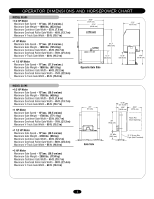
OPERATOR DIMENSIONS AND HORSEPOWER CHART MODEL SL585 • 1/2 HP Motor Maximum Gate Speed - 11"/sec. (27.9 cm/sec.) Maximum Gate Weight - 1000 lbs. (453.6 kg) Maximum Cantilever Gate Width - 25 ft. (7.6 m) Maximum Overhead Roller Gate Width - 45 ft. (13.7 m) Maximum V-Track Gate Width - 35 ft. (10.7 - LiftMaster SL595 | SL595 Manual - Page 4
servicing the general public. CLASS III - INDUSTRIAL/LIMITED ACCESS VEHICULAR GATE OPERATOR A vehicular gate operator (or system) intended for use in a industrial in both the open and close directions of gate travel. For Example: For a slide gate system that is installed on a single-family - LiftMaster SL595 | SL595 Manual - Page 5
for Exposed Rollers • Vertical Posts • Photoelectric Sensors • Instructional and Precautionary Signage 4. Install the gate operator only when: a. The operator is appropriate for the construction and the usage class of the gate. b. All openings of a horizontal swing gate are guarded or screened - LiftMaster SL595 | SL595 Manual - Page 6
SUGGESTED ENTRAPMENT PROTECTION DEVICE LOCATIONS GATE SYSTEM (MASTER/SECOND SLIDE GATE) Open Edge Gate 2 Open Edge STREET Photo eyes for close cycle Gate 1 Close Edge Photo eyes for open cycle Run twisted wire from loop to operator Interrupt (Safety) Loop 4'T(y1p.2icmal) 4'T(y1p.2icmal) - LiftMaster SL595 | SL595 Manual - Page 7
Mounted Gate Edge for Open Direction roller guards are available for installing over the rollers. • UL325 requires that, when used, contact sensors shall be Pinch-Point Hazard located at the leading edge, trailing edge, and be post mounted both inside and outside of a vehicular horizontal slide - LiftMaster SL595 | SL595 Manual - Page 8
made by a qualified individual. • DO NOT install ANY wiring or attempt to run the operator without consulting the wiring diagram. We recommend that you install an optional reversing edge BEFORE proceeding with the control station installation. • ALL power wiring should be on a dedicated circuit and - LiftMaster SL595 | SL595 Manual - Page 9
INSTALLATION PAD MOUNTING (SL585 ONLY) Figure 1 RETRO-FIT INSTALLATION The operator is shipped from the factory with the lower mounting Using Suitable Hardware To Secure Operator To Concrete Anchors Concrete Pad Drive and Idler Sprocket Toward Gate Side Power and Control Wiring Must Be Run In - LiftMaster SL595 | SL595 Manual - Page 10
POST MOUNTING (SL585 AND SL595) RETRO-FIT INSTALLATION The operators come from the factory configured to mount to an inside the frame post mount dimension of 26" (66 cm) (outside to outside of posts). The frame comes slotted to accommodate posts 24-1/8" (61 cm) to 26" (66 cm), outside to outside ( - LiftMaster SL595 | SL595 Manual - Page 11
to the operator or gate, DO NOT drive the limit (nuts) actuators on the shaft past their normal positions. Figure 1 WARNING Gate "Outside" "Inside" WARNING 1. Mount gate brackets to the vertical front and rear posts of the gate (Figure 1). 2. Remove the operator cover or open access door - LiftMaster SL595 | SL595 Manual - Page 12
DISCONNECT MODEL SL585 DISENGAGEMENT: RE-ENGAGEMENT: Rotate disconnect handle 90˚ to disengage. The gate may now be moved manually. Rotate handle back to original position. (Some operator output sprocket rotation may be required for engagement.) MODEL SL595 DISENGAGEMENT: RE-ENGAGEMENT: Open the - LiftMaster SL595 | SL595 Manual - Page 13
GL controller board's diagnostic and limit LEDs. When power is turned on, these LEDs should flash simultaneously for a few seconds. 3. Locate the 3-button control that is built into the electrical box. 4. Push the open button and observe the operator's behavior. The gate should begin opening. If - LiftMaster SL595 | SL595 Manual - Page 14
detected (gate edge or RPM sensor), gate will stop and alarm. Photo Eye Input: See Programming Section on page 15. This input will reverse a closing gate to the open limit. This input will not affect the Timer-to-Close. Activating this input when the gate is closing will have no effect. 14 GL Board - LiftMaster SL595 | SL595 Manual - Page 15
open or override open inputs. CONTROL BOARD ILLUSTRATION Main Terminal Wiring J4 Connector Master/Second Dip Switch #4 Master/Second Potentiometer Timer-to-Close Potentiometer Force Adjustment Dip Switch #2 Dip Switch #1 Diagnostic LED J2 Connector J5 Connector SAMS Relay Drive Troubleshooting - LiftMaster SL595 | SL595 Manual - Page 16
feature works in conjunction with the potentiometer located on the board. TIMER-TO-CLOSE ENABLED TIMER-TO-CLOSE DISABLED SAVE RT SW TTC SAVE RT SW TTC S1 S1 ON ON ON 1 2 34 ON 1 2 34 LT SL LT SL (Factory Default) SLIDE/SWING This switch selects slide or swing gate operation - LiftMaster SL595 | SL595 Manual - Page 17
9 10 11 12 13 14 15 16 17 18 19 20 24 Vac Control Board SINGLE PHASE ELECTRICAL BOX NOTE: See wiring diagrams shipped with accessory kit for additional information. NOTE: All controls that are to be used to operate the gate system, must be installed where the user cannot come into contact with the - LiftMaster SL595 | SL595 Manual - Page 18
the manual. Refer to instructions shipped with optional control devices for mounting, wiring, programming and adjustment. When using a remote control or Single Button Control Station in lieu of the Soft Open feature, perform the following modifications to the operator: 1. Remove the green wire from - LiftMaster SL595 | SL595 Manual - Page 19
to operate your gate operator. The opener will now operate when the push button on either the receiver or the remote control is pressed. Repeat Steps 2 and 3 for each remote control that will be used to operate the gate operator. TO ERASE ALL REMOTE CONTROL CODES Press and hold the "learn" button on - LiftMaster SL595 | SL595 Manual - Page 20
These terminals are intended for use with a loop detector and is primarily used on swing gate operators. This input protects cars by preventing the gate from moving off of the open or close limit when the shadow loop input is active. The control board senses commands using +24 Vdc from terminal - LiftMaster SL595 | SL595 Manual - Page 21
rod must be located within 3 feet from the gate operator. Use the proper type earth ground rod for your local area. The ground wire must be a single, whole piece of wire. Never splice two wires for the ground wire. If you should cut the ground wire too short, break it, or destroy its integrity - LiftMaster SL595 | SL595 Manual - Page 22
swing or slide gate will close followed by the barrier. SAMS WIRING 1. Install conduit between the BG770 and the SL585/595 for SAMS control wiring. 2. Run a 4-conductor cable in the conduit between the BG770 SL585/595. 3. Locate the SAMS relay terminals (J5) on the control board in the SL585/595 - LiftMaster SL595 | SL595 Manual - Page 23
by a LiftMaster professional. 10. SAVE THESE INSTRUCTIONS. DESCRIPATIVONERTISTSASEK MENT CHECK AT LEAST ONCE EVERY 3 MONTHS 6 MONTHS 12 MONTHS RPM Sensor (Hall Effect) Check for proper adjustment X X External Entrapment Check for proper operation X X Protection Systems Gate Caution - LiftMaster SL595 | SL595 Manual - Page 24
function is preprogrammed at factory. If either board or motor is replaced, the control board will need to be reprogrammed to "LEARN" the specific motor RPM profile of your operator, the red button "S3" is provided for this. This is important for accurate force control. Failure to do so may result - LiftMaster SL595 | SL595 Manual - Page 25
Diagnostic Meaning Cleared By Normal operation Single entrapment sensed Double entrapment Failed or no hall effect sensor Exceed maximum motor run time Limit fault Loss of communications between master and second during run mode Motor not learned N/A Control Input Hard Input* Removal of problem - LiftMaster SL595 | SL595 Manual - Page 26
factory plug-in loop detectors are working properly and appropriate loops are installed on the loop input terminals. ➤ Stand-Alone Operators: Make sure there is a jumper installed across the J4 connector. ➤ Master/Second Operation: Make sure that the master/second wiring is installed correctly and - LiftMaster SL595 | SL595 Manual - Page 27
loops are installed on the loop input terminals. OPERATOR HAS TROUBLE 1) Operator's manual release is engaged LEARNING THE MOTOR ➤ Make sure the manual release is not engaged. The operator's manual release, when engaged, will not allow the entrapment sensor to provide feedback to the control board - LiftMaster SL595 | SL595 Manual - Page 28
(T1) HEATER WIRING DIAGRAM FOR 208, 230, 460 AND 575V OPERATORS 24 Vac to operator controls FusFibuslee d3e.2A3. wires Green Ground Black (N) Black (T1) HEATER REPLACEMENT PARTS PART NUMBER 21-15453-1 50-18423 DESCRIPTION QTY. Transformer 100VA with 3.2A fuse 1 (208V, 230V and 460V models - LiftMaster SL595 | SL595 Manual - Page 29
screw, white wire to silver screw and green wire to green screw. 5. When using a remote control or Single Button Control Station in lieu of the Soft Open feature, perform the following modifications to the operator: 1. Remove the green wire from R4 of the radio block and mount the wire to terminal - LiftMaster SL595 | SL595 Manual - Page 30
For single phase 115v operation, there is an additional white wire from contactor (GL CONTROL BOARD) A2 to contactor B4 and the black wire from the transformer to contactor B4 goes to B6. 7. When using a remote control or single button control station in lieu of the soft open feature, perform the - LiftMaster SL595 | SL595 Manual - Page 31
external line monitoring device. 4. When using a remote control or Single Button Control Station in lieu of the Soft Open feature, perform the following modifications to the operator: 1. Remove the green wire from R4 of the radio block and mount the wire to terminal block TB1 position 6. 2. Move the - LiftMaster SL595 | SL595 Manual - Page 32
an external line monitoring system. 6. When using a remote control or single button control station in lieu of the soft open feature, perform the following modifications to the operator: • Remove the green wire from R4 of the radio block and mount the wire to terminal block TB1 position 6. • Move - LiftMaster SL595 | SL595 Manual - Page 33
- model SL585-100-53 K20-1150C-2P Motor - models SL585-150-11, SL585-150-21 10 23-3001 23-3005 VARIABLE PARTS On/off switch - 1 phase 115 208/230V On/off switch - 3 phase 01-34850 01-34850SP 01-34850FR NOT SHOWN Gate bracket Take up bolt Chain Bolt - 14" Owner's manual - English Owner's manual - LiftMaster SL595 | SL595 Manual - Page 34
ILLUSTRATED PARTS - MODEL SL585 SL585 ILLUSTRATED PARTS 2 K5 ( K75-34842) 9 7 8 K7 (K75-34791) K6 ( K75-34790) 10 K8 (K29-32410) 3 K3 (K75-34828) 3 6 K4 (K75-34824) 4 K3 (K75-34828) K9 (K75-18493) 4 K1 (71-B120G, 71-B208G, 71-B240G, 71-B575G) K10 (653509) 1 2 K2 (K75-10177) 34 - LiftMaster SL595 | SL595 Manual - Page 35
12 10-30699 Bracket mounting 13 K1C3196-3 Antenna 14 23-2016 Limit switch 15 13-10024 Limit nut 16 K74-G0589 RPM sensor (Hall Effect) kit 17 12-3601 Pillowblock bearing 18 39-10541 Clutch disk 23-34815 NOT SHOWN Stop/Reset button - located on enclosure door ITEM PART # K1 71-B120G 71 - LiftMaster SL595 | SL595 Manual - Page 36
ILLUSTRATED PARTS - MODEL SL595 SL595 ILLUSTRATED PARTS K7 (K75-18493) 10 3 11 6 8 7 5 1 4 2 5 K1 (71-B120G) (71-B208G) (71-B240G) 18 (71-B575G) K3 (K75-12858) 17 12 18 14 15 16 K2 (K75-18618) K5 (K72-35306) 13 K6 (K29-32410) K4 (K75-18620) 9 312HM Receiver Mounted to the - LiftMaster SL595 | SL595 Manual - Page 37
Overload - 1.8 to 2.6 AMP SL585-100-53, SL595-100-53 Overload - 2.6 to 3.7 AMP SL595-200-53 NOT SHOWN RPM Sensor (Hall Effect) ITEM K1 PART # SERVICE KITS DESCRIPTION K72-34818 Limit shaft kit (SL585 only) Complete with: Limit shaft, limit nuts, limit bearings, limit sprocket, shim washers - LiftMaster SL595 | SL595 Manual - Page 38
protection. MODEL AOMRON MODEL G65MG0204 G65MG0205 G65ME12C5 G65MGR205 G65MGS205 PHOTO-ELECTRIC CONTROLS DESCRIPTION Photocell/Electric Eye - 30' (9 m) Maximum Range SENSING EDGES DESCRIPTION Miller MG020 2-wire electric edge for gates. Sensitized on three sides. Requires mounting channel - LiftMaster SL595 | SL595 Manual - Page 39
NOTES 39 - LiftMaster SL595 | SL595 Manual - Page 40
SPANS AMERICA FOR INSTALLATION AND SERVICE INFORMATION, CALL OUR TOLL FREE NUMBER 1-800-528-2806 www.liftmaster.com WHEN ORDERING REPAIR PARTS PLEASE SUPPLY THE FOLLOWING INFORMATION: PART NUMBER DESCRIPTION MODEL NUMBER ADDRESS ORDER TO: THE CHAMBERLAIN GROUP, INC. Technical Support Group 6050
-
 1
1 -
 2
2 -
 3
3 -
 4
4 -
 5
5 -
 6
6 -
 7
7 -
8
-
9
-
10
-
11
-
12
-
13
-
14
-
15
-
16
-
17
-
18
-
19
-
20
-
21
-
22
-
23
-
24
-
25
-
26
-
27
-
28
-
29
-
30
-
31
-
32
-
33
-
34
-
35
-
36
-
37
-
38
-
39
-
40
 |
 |

CONTROLLER BOARD
GL
Serial # ________________________
(located on electrical box cover)
Installation Date__________________
2 YEAR WARRANTY
MODELS SL585 AND SL595 ARE FOR VEHICULAR
PASSAGE GATES ONLY AND ARE NOT INTENDED FOR
PEDESTRIAN PASSAGE GATE USE
MODEL SL585
HEAVY DUTY SLIDE GATE OPERATOR
MODEL SL595
HEAVY DUTY, HARSH ENVIRONMENT
SLIDE GATE OPERATOR