LiftMaster SW420 SW420 GL BOARD Manual
LiftMaster SW420 Manual
 |
View all LiftMaster SW420 manuals
Add to My Manuals
Save this manual to your list of manuals |
LiftMaster SW420 manual content summary:
- LiftMaster SW420 | SW420 GL BOARD Manual - Page 1
GLCONTROLLER BOARD MODEL SW420 LIGHT DUTY SWING GATE OPERATOR 2 YEAR WARRANTY Serial located on electrical box cover) Installation Date INTENDED FOR PROFESSIONAL INSTALLATION ONLY. VISIT WWW.LIFTMASTER.COM TO LOCATE A PROFESSIONAL INSTALLING DEALER IN YOUR AREA. THIS MANUAL IS TO BE LEFT WITH - LiftMaster SW420 | SW420 GL BOARD Manual - Page 2
(Hall Effect) Adjustment 18 Sequenced Access Management System (SAMS 19 Accessory Wiring 20-21 Control Board Illustration 22 Controller Programming and Features 23-24 Program Settings 25-26 TROUBLESHOOTING 27-28 MAINTENANCE Operator Maintenance 29 Single Phase Wiring Diagram 30 Repair Parts - LiftMaster SW420 | SW420 GL BOARD Manual - Page 3
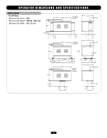
OPERATOR DIMENSIONS AND SPECIFICATIONS MODEL SW420 • 1/3 HP Motor Maximum Gate Starts - 10/hr. Maximum Gate Weight - 300 lbs. (136.1 kg) Maximum Gate Width - 12 ft. (3.7 m) 1-3/8" 11-3/4" 18-3/16" Post Mount (standard) 11-5/8" 3-3/16" 3" (Nominal) 1-3/8" 14-5/8" 18-3/16" Pad Mount ( - LiftMaster SW420 | SW420 GL BOARD Manual - Page 4
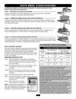
UL325 MODEL CLASSIFICATIONS The SW420 is intended for use with vehicular swing gates. The opener can be used in Class I, Class II, Class III and Class IV applications. CLASS I - RESIDENTIAL VEHICULAR GATE OPERATOR A vehicular gate operator (or system) intended for use in a home of one-to-four single - LiftMaster SW420 | SW420 GL BOARD Manual - Page 5
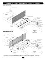
SYSTEM Telephone Entry System STREET Interrupt (Safety) Loop Photo eye for close cycle DUAL SWING GATE SYSTEM Photo eye for open cycle Run twisted wire* from loop to operator Seal Loops* Shadow Loop Interrupt (Safety) Loop 4' (1.2 m) Typical 1-1/2" (37 mm) Loop Wire* Layer 1/4" (6 mm) or larger - LiftMaster SW420 | SW420 GL BOARD Manual - Page 6
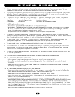
. Swinging gates shall not open into public access areas. 7. The gate must be properly installed and work freely in both directions prior to the installation of the gate operator. 8 Controls intended for user activation must be located at least six feet (6') away from any moving part of the gate - LiftMaster SW420 | SW420 GL BOARD Manual - Page 7
II and Class III vehicular horizontal swing gates: 4.1.1 Gates shall be designed, constructed and installed so as not to create an entrapment area between the gate and the supporting structure or other fixed object when the gate moves toward the fully open position, subject to the provisions in - LiftMaster SW420 | SW420 GL BOARD Manual - Page 8
MUST be installed to protect anyone who may come near a moving gate. • Locate entrapment protection devices to protect in BOTH the open and close gate cycles. • Locate entrapment protection devices to protect between moving gate and RIGID objects, such as posts. • A swinging gate shall NOT open into - LiftMaster SW420 | SW420 GL BOARD Manual - Page 9
INSTALLATION POST MOUNTING 1. Locate and anchor two posts made of 3" (7.6 cm) outer diameter heavy walled pipe. Posts should be parallel and square to the gate. IMPORTANT NOTE: The distance between mounting posts and the relative location of the operator to the gate and fence is critical. 2. Locate - LiftMaster SW420 | SW420 GL BOARD Manual - Page 10
INSTALLATION PAD MOUNTING 1. Layout the concrete pad (Figure 1). IMPORTANT NOTE: The relative location of the operator to the fence and the gate is critical. Be sure that the measurements for operator mounting are taken from the centerline of the fence and of the gate hinge. 2. Locate electrical - LiftMaster SW420 | SW420 GL BOARD Manual - Page 11
INSTALLATION PEDESTAL MOUNTING 1. Locate and anchor pedestal. Pedestal should be parallel and square to the gate. IMPORTANT NOTE: The distance between mounting pedestal and the relative location of the operator to the gate and fence is critical. 2. Locate electrical conduit, as required, prior to - LiftMaster SW420 | SW420 GL BOARD Manual - Page 12
. Figure 1 Arm Kit 307072703R CAUTION If the arm stop is installed incorrectly, the gate will be prevented from opening and damage to the operator may result! 6. Assemble the gate bracket to the extension arm as shown. 7. Put the gate in the fully closed position and extend the arm AVERT assembly - LiftMaster SW420 | SW420 GL BOARD Manual - Page 13
INSTALLATION MECHANICAL DISCONNECT The operator can be disconnected from the gate, so the gate can be manually opened or closed. Disconnect the control arm from the drive hub by removing the hairpin cotter and then the clevis pin and allowing the manual release pin to drop down through the hub. The - LiftMaster SW420 | SW420 GL BOARD Manual - Page 14
service. AVERTISSEMENT • Disconnect power at the fuse box BEFORE proceeding. Operator operator. ATTENTION POWER WIRING INSTALLATION Wiring SpecifiAcatiVonEs (SRTRTANIDSEDSCEOPMPEREWNIRET) On a Dual Gate System, each unit must be installed must be reviewed for suitability of wire installation. All - LiftMaster SW420 | SW420 GL BOARD Manual - Page 15
BLACK • GROUND, GREEN Wire Nut Connections (See Instructions) Power Wiring Conduit STOP/RESET BUTTON CONTROL WIRING (REQUIRED) 1. This control will function as a Stop/Reset command and is to be wired within line of sight of the gate. The operator will not function unless this circuit is completed - LiftMaster SW420 | SW420 GL BOARD Manual - Page 16
changing the code setting or replacing To prevent possible SERIOUS INJURY or DEATH, the use of the battery. THERE ARE NO OTHER USER SERVICEABLE PARTS. CAUTION AVERTISSEMENT WARNING CONSTANT OPERATION on residential openers is PROHIBITED. Tested to Comply with FCC Standards FOR HOME OR OFFICE USE - LiftMaster SW420 | SW420 GL BOARD Manual - Page 17
arm from gate bracket so gate is no longer connected to operator. Push manual release pin OPEN LIMIT SWITCH 8. Turn on power. Press OPEN button (if installed) or connect terminals 5 & 7 on J1 terminal strip. Gate should open. If gate does not open the open limit cam may be already actuating open - LiftMaster SW420 | SW420 GL BOARD Manual - Page 18
) ADJUSTMENT NOTE: Normally the RPM sensor (hall effect) does not need adjustment, but may go out of alignment due to shipping vibration or rough handling. These operators use an internal entrapment protector system. This system consists of the control board, magnet, and RPM sensor. It may become - LiftMaster SW420 | SW420 GL BOARD Manual - Page 19
many gate operator types and the slide or swing gates allow you to effectively seal off the perimeter of the complex you are planning to secure. NOTE: Connect all entry devices to the slide or swing gate. If using a device, such as a 7-day timer, to latch the slide or swing gate open during high - LiftMaster SW420 | SW420 GL BOARD Manual - Page 20
gives the user the ability to close the gate by activating the remote control when the gate is on the open limit. J1 Terminals 2 & 5 - Shadow Loop Input These terminals are intended for use with a loop detector and is primarily used on swing gate operators. This input protects cars by preventing the - LiftMaster SW420 | SW420 GL BOARD Manual - Page 21
of site of the gate. This input functions to stop the gate or to reset the gate after an entrapment fault. NOTE: This input uses a normally closed circuit and the operator will not run until a stop control is installed. STOP/RESET BUTTON WIRING R1 R2 R3 R4 3 5 OPEN CLOSE STOP STOP J1 Terminals - LiftMaster SW420 | SW420 GL BOARD Manual - Page 22
BOARD ILLUSTRATION Main Terminal Wiring J4 Connector Master/Second Dip Switch #4 Master/Second Potentiometer Timer-to-Close Potentiometer Force Adjustment Dip Switch #2 Dip Switch #1 Diagnostic LED J2 Connector J5 Connector SAMS Relay Drive Troubleshooting LEDs J1 Terminal Troubleshooting - LiftMaster SW420 | SW420 GL BOARD Manual - Page 23
On No Flash Normal operation Single entrapment sensed Double entrapment Failed or no hall effect sensor Exceed maximum motor run time Limit fault Loss of communications between master and second during run mode Motor not learned N/A Control Input Hard Input* Removal of problem Hard Input* Control - LiftMaster SW420 | SW420 GL BOARD Manual - Page 24
ADJUSTMENT CONTROL BOARD PROGRAMMING AND FEATURES (CONTINUED) RELAY DRIVE TROUBLESHOOTING LEDS There are 5 troubleshooting LEDs on troubleshooting LEDs. LED D11 D13 D15 D17 (Green) D19 D21 D24 D29 D31 LED NAME Radio Shadow Hard Close Stop Soft Open Hard Open Interrupt (Safety) Loop Obstruction Open - LiftMaster SW420 | SW420 GL BOARD Manual - Page 25
For all S1, S2 and S4 switch settings to take effect, the Save Mode switch must be set to the off /SWING This switch selects slide or swing gate operation, in order to optimize gate behavior for specific application. SL = Slide • SW = Swing RIGHT/LEFT OPERATION This switch selects the gate opening - LiftMaster SW420 | SW420 GL BOARD Manual - Page 26
limit when the edge is activated during the opening cycle. CLED OPED WARN MAG CLED OPED WARN MAG S2 ON ON 1 2 34 S2 ON ON 1 2 34 PH PH PH PH MASTER/SECOND SYSTEMS Dual Gate Communications The control board is capable of running the operator in a master or second mode depending on (S4 - LiftMaster SW420 | SW420 GL BOARD Manual - Page 27
TROUBLESHOOTING SYMPTOM POSSIBLE CAUSES SOLUTION Operator fails to run. No Stop Control. Check the green LED (D17) on control board. If the green LED is off, check to make sure a stop control has been installed across terminals J1-3 & J1-5 of the control board. Fault in the operator. Check - LiftMaster SW420 | SW420 GL BOARD Manual - Page 28
the gate. Observe red LEDs D29 and D31. Both LEDs will indicate the activation of entrapment protection devices on terminals J1-9 & J1-10 on the control board. Remove the devices and retest. If the operator now runs without fault, check those accessories as well as their wiring. The Hall Effect - LiftMaster SW420 | SW420 GL BOARD Manual - Page 29
by a LiftMaster professional. 10. SAVE THESE INSTRUCTIONS. AVERTISSEMENT DESCRIPTION TASK CHECK AT LEAST ONCE EVERY 3 MONTHS 6 MONTHS 12 MONTHS RPM Sensor (Hall Effect) Check for proper adjustment X X External Entrapment Check for proper operation X X Protection Systems Gate Caution - LiftMaster SW420 | SW420 GL BOARD Manual - Page 30
STOP INTERRUPT LOOP ENTRAPMENT OPEN ENTRAPMENT CLOSE TO PRIMARY/SECONDARY UNIT NOTES: 1) TRANSFORMER PRIMARY VOLTAGE SAME AS OPERATOR LINE VOLTAGE 24V ON GL PC BOARD APPLICATIONS: CONTROL WIRING TYPE - GL FIELD WIRING & ADJUSTMENTS MODEL TYPES: HORSEPOWER: VOLTAGE/PHASE: SW420 1/3 115V & - LiftMaster SW420 | SW420 GL BOARD Manual - Page 31
service representative regarding availability of individual components. Refer to page 36 for all repair part ordering information. Complete Electrical Panel Replacement Kits To order a complete electrical box replacement kit, add a K- prefix to the model number of your operator. For example: SW420 - LiftMaster SW420 | SW420 GL BOARD Manual - Page 32
ILLUSTRATED PARTS A4 A8 A6 1 8 D12 D10 D D21 D22 D6 D13 D16 D3 D11 5 4 3 A11 A5 A9 A12 9 D23 D5 D8 D18 D9 D1 D15 D19 D20 D17 D14 D4 D2 D7 A7 A10 A7 A11 A7 A3 A A2 A1 E1 E5 E10 E14 E7 E15 E11 E12 E2 E8 E14 E E4 E3 E8 2 E9 E6 E13 6 Optional 7 Optional 32 - LiftMaster SW420 | SW420 GL BOARD Manual - Page 33
AOMRON MODEL G65MG0204 G65MG0205 G65ME12C5 G65MGR205 G65MGS205 PHOTOELECTRIC CONTROLS DESCRIPTION Photocell/Electric Eye - 30' (9 m) Maximum Range SENSING EDGES DESCRIPTION Miller MG020 2-wire electric edge for gates. Sensitized on three sides. Requires mounting channel (4' [1.2 m] long). Miller - LiftMaster SW420 | SW420 GL BOARD Manual - Page 34
9 10 11 12 24 Vac GL Board NOTE: SEE WIRING DIAGRAMS SHIPPED WITH KIT FOR ADDITIONAL INFORMATION. SEE OWNERS MANUAL FOR WIRING DISTANCES AND WIRE GAUGE INFORMATION. WARNING: All controls that are to be used to operate the gate system, MUST be installed where the user cannot come into contact with - LiftMaster SW420 | SW420 GL BOARD Manual - Page 35
OPERATOR NOTES 35 - LiftMaster SW420 | SW420 GL BOARD Manual - Page 36
SPANS AMERICA FOR INSTALLATION AND SERVICE INFORMATION CALL OUR TOLL FREE NUMBER: 1-800-528-2806 www.liftmaster.com WHEN ORDERING REPAIR PARTS PLEASE SUPPLY THE FOLLOWING INFORMATION: PART NUMBER DESCRIPTION MODEL NUMBER ADDRESS ORDER TO: THE CHAMBERLAIN GROUP, INC. Technical Support Group 6050
-
 1
1 -
 2
2 -
 3
3 -
 4
4 -
 5
5 -
 6
6 -
 7
7 -
8
-
9
-
10
-
11
-
12
-
13
-
14
-
15
-
16
-
17
-
18
-
19
-
20
-
21
-
22
-
23
-
24
-
25
-
26
-
27
-
28
-
29
-
30
-
31
-
32
-
33
-
34
-
35
-
36
 |
 |

CONTROLLER BOARD
GL
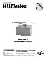
MODEL SW420 IS FOR VEHICULAR PASSAGE GATES ONLY AND
IS NOT INTENDED FOR PEDESTRIAN PASSAGE GATE USE.
INTENDED FOR PROFESSIONAL INSTALLATION ONLY.
VISIT WWW.LIFTMASTER.COM TO LOCATE A PROFESSIONAL
INSTALLING DEALER IN YOUR AREA.
THIS MANUAL IS TO BE LEFT WITH THE PROPERTY OWNER.
MODEL SW420
LIGHT DUTY SWING GATE OPERATOR
Serial #_________________________
(located on electrical box cover)
Installation Date __________________
2 YEAR WARRANTY