LiftMaster SW420 SW420 S3 BOARD Manual
LiftMaster SW420 Manual
 |
View all LiftMaster SW420 manuals
Add to My Manuals
Save this manual to your list of manuals |
LiftMaster SW420 manual content summary:
- LiftMaster SW420 | SW420 S3 BOARD Manual - Page 1
Installation and Maintenance Instructions Swing Gate Operator Model SW420 Doc 01-G0610 Rev A - LiftMaster SW420 | SW420 S3 BOARD Manual - Page 2
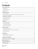
Information 4 Parts Supplied 4 Model Classifications 4 Specifications 5 Safety Information 6 Safety Instructions 6 Safety Precautions for Swing Gates and Ornamental "Grill Type" Gates 8 Preparing the Installation 9 Pre-Installation Check List 9 Wiring Specifications 9 Operator Preparation - LiftMaster SW420 | SW420 S3 BOARD Manual - Page 3
Features and Program Troubleshooting review 30 Parts List - SW420 31 Warranty Policy 33 IMPORTANT! Please leave this manual at the job site, preferably with the end user or facility manager. Read and follow all instructions. This gate operator is intended for use on a gate that swings in an arc - LiftMaster SW420 | SW420 S3 BOARD Manual - Page 4
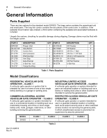
shipping. Damage claims must be filed with the freight carrier. PART # SW420 1: Parts Supplied Model Classifications RESIDENTIAL VEHICULAR GATE OPERATOR - CLASS 1 A vehicular gate operator or service the general public. RESTRICTED ACCESS VEHICULAR GATE OPERATOR - CLASS 4 A vehicular gate operator - LiftMaster SW420 | SW420 S3 BOARD Manual - Page 5
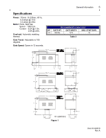
cap. Speed - 1000 rpm Current - 5.2A @ 115v. 2.6A @ 230v. Overload: Automatic resetting thermal. Gate Travel: Adjustable to 105 degrees. Gate Speed: Opens in 12 seconds. RECOMMENDED CAPACITIES HP GATE WT. GATE WIDTH MAX. STARTS/HR. 1/3 300 lbs. 12 ft. 10 Table 3 01-G0610F2 Figure 1 Doc 01 - LiftMaster SW420 | SW420 S3 BOARD Manual - Page 6
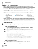
in design. 7 Confirm gate moves freely before installation of operator. 8 Repair or service worn or damaged gate hardware before installation of operator. 9 To avoid installation hazards, review the gate system operation and installation procedures, such as manual disconnect mechanism procedure. 10 - LiftMaster SW420 | SW420 S3 BOARD Manual - Page 7
. 2 Train end user about basic functions and safety features of gate system. 3 Leave Installation and Maintenance Manual and Safety Information with end user. FOR GATE OPERATORS USING NON-CONTACT SENSOR(S) See instruction supplied with sensor for proper placement. Precautions must be taken to - LiftMaster SW420 | SW420 S3 BOARD Manual - Page 8
beams must be incorporated into the swing gate system to assist in the protection of people who may come near the gate operating system. Also, injuries can occur when people put their hands and arms through openings in a grill type gate and it is operated. This potential hazard can be averted - LiftMaster SW420 | SW420 S3 BOARD Manual - Page 9
the Installation 9 Preparing the Installation Pre-Installation Check List Check the gate. It MUST operate smoothly and freely. If necessary, lubricate the hinges, adjust or repair the gate prior to operator installation. The gate MUST be level. Double check the size and weight of the gate to - LiftMaster SW420 | SW420 S3 BOARD Manual - Page 10
Installation Operator Preparation 1 Open the service cover on the operator by removing 6 screws and pulling down and out. Inside you will find the electrical enclosure stored vertically. All the electrical connections for controls that the installer wire entry. The SW420 is provided with (6) - LiftMaster SW420 | SW420 S3 BOARD Manual - Page 11
and fence is critical. Be sure that the measurements for operator mounting are taken from the centerline of the fence and of the gate hinge. 4 Pour cement to secure mounting posts and allow to set for (2) days before installing power unit. 5 Knock out the post mount holes on each If mentioned - LiftMaster SW420 | SW420 S3 BOARD Manual - Page 12
12 Installation SW420 POST PARALLEL MOUNT 01-G0610F6 Figure 5 SW420 POST PERPENDICULAR MOUNT Doc 01-G0610 Rev A REAR OF CABINET SPECIAL BOLT USE TOOL PROVIDED (11-2754) TO INSERT SPECIAL NUT IN REAR HOLES. 01-G0610F7 Figure 6 - LiftMaster SW420 | SW420 S3 BOARD Manual - Page 13
installing power unit. IMPORTANT NOTE: The relative location of the operator to the fence and the gate is critical. Be sure that the measurements for operator brackets. Pivot Gate Fence Line Pivot Gate Fence Line 18"x30" Pad Minimum 3/8" L-Bolts SW420 PAD PARALLEL MOUNT SW420 PAD PERPENDICULAR - LiftMaster SW420 | SW420 S3 BOARD Manual - Page 14
gate hinge. 5 Pour cement to secure pedestal in place. Allow concrete to set for (2) days before installing power unit. 6 After concrete has set, secure the operator PIN FENCE LINE GATE GATE SW420 PEDESTAL PARALLEL MOUNT PEDESTAL 24" DEEP IN-GROUND MINIMUM SW420 PEDESTAL PERPENDICULAR MOUNT - LiftMaster SW420 | SW420 S3 BOARD Manual - Page 15
so that the arm assembly is level and able to operate smoothly. 9 The gate bracket must be installed on a structural member of the gate. If required, install a horizontal support on the gate at the appropriate height. 10 Attach the gate bracket with U-bolts or by welding. Doc 01-G0610 Rev A - LiftMaster SW420 | SW420 S3 BOARD Manual - Page 16
16 Installation 85-FW-38S 01-G0610F10 Figure 9 Doc 01-G0610 Rev A 01-G0610F11 Figure 10 - LiftMaster SW420 | SW420 S3 BOARD Manual - Page 17
System Features System Features 17 01-G0610F12 Figure 11: SW420 CONTROLLER Visible/Audible Devices ACTIVITY LED Steady indication when gate is at either open or close limit. 1 flash per second when gate is off a limit in normal operation. 2 flashes per second when entrapment level one has occurred - LiftMaster SW420 | SW420 S3 BOARD Manual - Page 18
in time delay to close. Either a manual device such as a pushbutton within site of the gate and operator, or the stop button supplied with the operator must be activated to resume the operator back to its normal operation. Circuitry OPEN ONLY CIRCUIT Separate open circuits for line-of-sight devices - LiftMaster SW420 | SW420 S3 BOARD Manual - Page 19
-G0610F13 Figure 13: Main Control Board Switch #1: Operator Programming Refer to Table 5. POLE #1: SINGLE/CLOSE BUTTON ON = Close button only OFF = Open/Close button POLE #2: RIGHT HAND / LEFT HAND ON = Left Hand (hate will open to the left) OFF = Right Hand (gate will open to the right-inside of - LiftMaster SW420 | SW420 S3 BOARD Manual - Page 20
jumper from bottom two pins to top two pins. Then set time per the chart above (Table 5). 2 During normal operation, if the operator stops on a limit, or mid travel, the operator will time out per the chart below and automatically close. 3 To lock the timer to close program and disable, simply - LiftMaster SW420 | SW420 S3 BOARD Manual - Page 21
extension arm from gate bracket so that the gate is no longer connected to the operator. 2 Push the manual release pin up free moving on the shaft. AUXILIARY OPEN LIMIT CAM & COLLAR LIMIT A CAM & COLLAR LIMIT B CAM & COLLAR LIMIT SWITCH A LIMIT SWITCH B DIRECTION OF GATE TO OPEN Right Left OPEN - LiftMaster SW420 | SW420 S3 BOARD Manual - Page 22
installation you have (left or right hand to move in the direction that opening). The OPEN/CLOSE button is a constant pressure would close the gate operation) on the control terminal strip. The gate should start to open. If it does not, the open limit cam may be already actuating the open limit - LiftMaster SW420 | SW420 S3 BOARD Manual - Page 23
before placing hands or tools in operator or near drive shaft and control arm. The close limit switch should stop the gate at a point where the control arm past the 180-degree position, the gate is effectively locked against any attempts to push it open from the outside. Refer to Figure 10. The - LiftMaster SW420 | SW420 S3 BOARD Manual - Page 24
the manual. Installation device instructions - always follow the instructions provided by the manufacturer when installing and adjusting any control device. If these instructions are contrary to the advice given here, call for assistance. WARNING All controls that are to be used to operate the gate - LiftMaster SW420 | SW420 S3 BOARD Manual - Page 25
Manual Operation 25 Manual Operation To operate the gate manually, disconnect the control arm from the drive hub by removing the hairpin cotter and then the clevis pin and allowing the manual release pin to drop down through the hub. The arm should now be free and the gate can be opened and closed - LiftMaster SW420 | SW420 S3 BOARD Manual - Page 26
systems Gate caution signs Sprockets & pulleys Gate Accessories Electrical Frame bolts Total unit ACTION Check for proper operation Check proper operation Inspect all wire connections Check for tightness Inspect for wear or damage Table 6 CAUTION When servicing, always disconnect operator from - LiftMaster SW420 | SW420 S3 BOARD Manual - Page 27
Troubleshooting 27 Troubleshooting When troubleshooting, one of the first things to do is try to isolate the problem area. The five (5) main areas to check out are: Power Accessories Operator's Primary Voltage Operator's Low Voltage Gear Reducer 1. Power Always use extreme caution! Some possible - LiftMaster SW420 | SW420 S3 BOARD Manual - Page 28
will hopefully isolate which item is causing the problem. 2B. If an accessory item is being used as an access control device (used to open or close), falls in the closed position or sends out a continuous signal. The operator will hold the gate in one position until the signal from the accessory - LiftMaster SW420 | SW420 S3 BOARD Manual - Page 29
rubbing during operation. Also check the sensors and magnets for debris that would affect the signal. There are no repairable parts for the problem when in actuality it is just a missed or wrong program setting. Make sure that all the connections wires on the "J1" terminal board are installed - LiftMaster SW420 | SW420 S3 BOARD Manual - Page 30
assistance, make sure you have the gate operator model number, voltage, phase, horsepower and a list of all accessories that are attached to the operator. Features and Program Troubleshooting Review The internal obstruction sensor (r.p.m. sensor) will cause the operator to either stop or reverse if - LiftMaster SW420 | SW420 S3 BOARD Manual - Page 31
Parts List - SW420 12-10715 10-2701-T 82-PX08-10T 82-PX10-26 Parts List - SW420 31 07-2704 07-2703 12-10715 24-24-1 24-24-1 10-2705-T 01-G0610F18 Figure 19 Doc 01-G0610 Rev A - LiftMaster SW420 | SW420 S3 BOARD Manual - Page 32
-G0609 74-G0684 74-SW420 75-G0090 75-G0552 76-G0564 Description STOP BUTTON ARM EXTENSION ARM ARM STOP ARM HUB GATE BRACKET TAN HOUSING ASSY DEEP 2 OHM RESISTOR w/MTG BRACKET HALL EFFECT BOARD (N) 70MFD 220V CAPACITOR ALARM HIGH OUTPUT W/DIODE (N) HALL EFFECT SENSOR (N) NYLON SENSOR SPACER (N) - LiftMaster SW420 | SW420 S3 BOARD Manual - Page 33
free parts will be repaired or replaced with new or factory-rebuilt parts at Seller's sole option. Authorization instructions PART. THIS LIMITED WARRANTY DOES NOT COVER NON-DEFECT DAMAGE, DAMAGE CAUSED BY IMPROPER INSTALLATION, OPERATION LIABILITY IN CONNECTION WITH THE SALE OF THIS PRODUCT. Some - LiftMaster SW420 | SW420 S3 BOARD Manual - Page 34
by copyright and contain information proprietary to LiftMaster. FOR TECHNICAL SUPPORT TO ORDER REPAIR PARTS Call our toll free numbers: Call our toll free numbers: (800) 323-2276 (800) 998-9197 (800) 528-2806 (800) 998-9197 Installation and service information is available six days a week
-
 1
1 -
 2
2 -
 3
3 -
 4
4 -
 5
5 -
 6
6 -
 7
7 -
8
-
9
-
10
-
11
-
12
-
13
-
14
-
15
-
16
-
17
-
18
-
19
-
20
-
21
-
22
-
23
-
24
-
25
-
26
-
27
-
28
-
29
-
30
-
31
-
32
-
33
-
34
 |
 |

Doc 01-G0610
Rev A
Installation and Maintenance
Instructions
Swing Gate Operator
Model SW420