LiftMaster T T LOGIC VERSION 2 Manual
LiftMaster T Manual
 |
View all LiftMaster T manuals
Add to My Manuals
Save this manual to your list of manuals |
LiftMaster T manual content summary:
- LiftMaster T | T LOGIC VERSION 2 Manual - Page 1
'S MANUAL MODEL T LOGIC CONTROL (VER. 2.0) INDUSTRIAL DUTY DOOR OPERATOR LOGIC LCONTROL FACTORY SET C2 Wiring See pages 15 and 16 for other wiring configurations PATENT PENDING The Maintenance Alert System TM allows the installer to set an internal Maintenance Cycle Counter. An LED on the 3-button - LiftMaster T | T LOGIC VERSION 2 Manual - Page 2
16 RPM Sensor 17 Maximum Run Timer 17 Maintenance Alert System 18 OPTIONAL PROGRAMMING Mid Stop 18 Timer to Close 19 Red Green Warning Lights 19 Board Illustration 20 REPLACEMENT PARTS & MAINTENANCE Trouble Shooting Guide 21 & 22 Maintenance Schedule 23 Customer Service Contact Information - LiftMaster T | T LOGIC VERSION 2 Manual - Page 3
modes. LIMIT ADJUST Linear driven, fully adjustable screw type cams. Adjustable to 24 feet. MECHANICAL DRIVE REDUCTION Primary: Heavy duty (5L) V-Belt. Secondary: #41 chain/sprocket. Output: #48 chain (1/3 &1/2Hp) or #41 chain (3/4 &1Hp) OUTPUT SHAFT SPEED:.....140 R.P.M. DOOR SPEED 11 - LiftMaster T | T LOGIC VERSION 2 Manual - Page 4
SERIOUS PERSONAL INJURY OR DEATH. CALL A PROFESSIONAL DOOR SERVICEMAN TO MOVE OR ADJUST DOOR CAUTION SPRINGS OR HARDWARE. TRACK ASSEMBLY 1. Using the 3/8"-16 x 3/4 " bolts and flange hex nuts supplied, assemble the operator track by installing and tightening the track spacer brackets. Position the - LiftMaster T | T LOGIC VERSION 2 Manual - Page 5
chain, or support from the floor. Now open garage door slowly, being careful not to dislodge the temporary support. Using the door as a support, place a level against the rail and shim the operator until it is horizontal. Make sure that the operator is aligned with the center line of the door. Guide - LiftMaster T | T LOGIC VERSION 2 Manual - Page 6
mounting of the support brace(s) to the powerhead, Four holes (clearance up to 3/8" bolts) are located on each side close the door and move the trolley slider to within (2") two inches of the front idler. 2. Latch the straight door arm to the fixed roll pin in the trolley carriage. Make sure the open - LiftMaster T | T LOGIC VERSION 2 Manual - Page 7
as door fully seats at the floor. CLOSE Limit Switch WARNING TO AVOID SERIOUS PERSONAL INJURY OR DEATH FROM ELECTROCUTION, DISCONNECT ELECTRIC POWER BEFORE MANUALLY MOVING LIMIT NUTS. If other problems persist, call our toll-free number for CAUTION assistance - 1-800-528-2806. OPEN Limit Switch - LiftMaster T | T LOGIC VERSION 2 Manual - Page 8
number on the back of this manual. DO NOT INSTALL ANY WIRING OR ATTEMPT TO RUN THIS OPERATOR WITHOUT CONSULTING THE WIRING DIAGRAM. IMPORTANT SAFETY NOTES WARNINGWARNING WARNINGWARNING INSTALL THE CONTROL STATION IN LINE OF SIGHT WITH THE DOOR, BUT AWAY FROM THE DOOR AND ITS HARDWARE. IF CONTROL - LiftMaster T | T LOGIC VERSION 2 Manual - Page 9
reset the timer to close. However, for additional door control from a 3 button transmitter, a commercial three-channel radio receiver (with connections for OPEN/CLOSE/STOP) is recommended. Control Station 4 Feet Approximate Optional Controls Maintenance Alert SystemTM If light is Flashing, it is - LiftMaster T | T LOGIC VERSION 2 Manual - Page 10
Straight Door Arm Assembly Chain Door Curved Door Arm NOTICE Emergency Release Handle TO DISCONNECT DOOR FROM OPENER Emergency Disconnect Door Arm Pull emergency release handle straight down. Emergency disconnect will open. TO RECONNECT DOOR ARM TO TROLLEY Emergency Disconnect Door Arm - LiftMaster T | T LOGIC VERSION 2 Manual - Page 11
door by hand during travel. 4. Reinstall Cotterpin. The Auxiliary Reversal System works in tandem with the adjustable clutch to detect if a closing door meets an obstruction. If an obstruction is met and causes the clutch to slip, the Auxiliary Reversal System will return the door to the full open - LiftMaster T | T LOGIC VERSION 2 Manual - Page 12
STANDARD POWER & CONTROL CONNECTION DIAGRAM Logic Control Board (VER. 2.0) - 115V, 208, 230V, 1Ph Logic Control Board (VER. 2.0) - 208, 230V, 380V, 460V, 3Ph 12 - LiftMaster T | T LOGIC VERSION 2 Manual - Page 13
Dip Switch Functions and Programming Procedures 2) TO REVERSE MOTOR DIRECTION 115 VOLTS: ALWAYS EXCHANGE PURPLE & GRAY ALL VOLTS & PHASES. 230 VOLTS: INTERCHANGE PURPLE (E10) & GRAY (E15) WIRES AT LOGIC BOARD. * - BLUE WIRE MUST BE INSULATED ON 230V 1PH. **- Transformer Primary Voltage same as Line - LiftMaster T | T LOGIC VERSION 2 Manual - Page 14
See Owner's Manual for Dip Switch Functions and Programming Procedures 2) TO REVERSE MOTOR DIRECTION: INTERCHANGE ANY 2 OF THE 3 POWER WIRES AT L1, L2 & L3, OR EXCHANGE PURPLE & GRAY MOTOR LEADS AT BOARD CONNECTIONS E17 & E6 (3PH UNITS ONLY). **- Transformer Primary Voltage same as Line Voltage. 14 - LiftMaster T | T LOGIC VERSION 2 Manual - Page 15
), Close Limit Switch (CLS) and Sensing Limit Switch (SLS). Refer to page 7 for limit switch adjustment instructions. Logic Control Pushbuttons Open, Close, Stop Open, Close and Stop buttons are mounted directly on the Logic Control board. This will provide easy programming ability and door control - LiftMaster T | T LOGIC VERSION 2 Manual - Page 16
ON FSTS Momentary button contact for open, close and stop. Radio controls allowing open, close and stop. User set midstop. User set Timer To Close. The FSTS single button station opens the door to the full open limit bypassing the mid stop and activates the Timer To Close, putting the operator - LiftMaster T | T LOGIC VERSION 2 Manual - Page 17
. LiftMaster recommends the use of safety devices for primary safety protection. To Program: 1. The open and close limits must be set before setting the RPM sensor. 2. Start with the door closed and turn all dip-switches to the off position. 3. Press open then press and hold the "learn" button on - LiftMaster T | T LOGIC VERSION 2 Manual - Page 18
cycles to Maintenance Alert 4. Press "open" for every 5,000 cycles the operator should wait before System Activation flashing the LED. Timer. 5. Return the dip switches to your regular wiring type (C2, B2, etc.) and close the door. ON ON EXAMPLE: The door is being installed with 30 thousand - LiftMaster T | T LOGIC VERSION 2 Manual - Page 19
the amount of time that a warning light will flash before the Timer To Close will activate the door to close. Benefit: Advanced warning of door closure helps prevent traffic collisions with the door. To Program: 1. Set the dip switches to "set Timer To Close" 2. Press stop for every additional - LiftMaster T | T LOGIC VERSION 2 Manual - Page 20
LOGIC 2.0 PCB BOARD ILLUSTRATION RPM LEARN BUTTON (SEE PAGE 17) HEAT SINK POWER WIRING TERMINAL BLOCK (SEE PAGES 8-9) DIP SWITCH (SEE PAGES 8-9) CONTROL WIRING TERMINAL BLOCK (SEE PAGES 8-9) OPEN, CLOSE, STOP BUTTONS 20 - LiftMaster T | T LOGIC VERSION 2 Manual - Page 21
b) Motor is malfunctioning RESOLUTION Reset the RPM sensor. Also verify that the software is version 260 or better. Order replacement chips from Parts and Service. Reset the Maximum Run Timer Reset the mid-stop by programming it to be at the open limit. a) Remove the obstruction, check the safety - LiftMaster T | T LOGIC VERSION 2 Manual - Page 22
as each control button is pressed. The LEDs should light with each Open, Close, and Single Button Control command. The Stop should turn off the LED. 3. Activate the limit switches to verify functionality. Also watch the LED's during door travel to check for over active limit switches. 4. Disconnect - LiftMaster T | T LOGIC VERSION 2 Manual - Page 23
MONTHS OR 5,000 CYCLES Drive Chain Check for excessive slack. Check & adjust as required. Lubricate l Sprockets Check set screw tightness l Clutch Check & adjust as required Belt Check condition & tension Fasteners Check & tighten as required Manual Disconnect Check & Operate Bearings - LiftMaster T | T LOGIC VERSION 2 Manual - Page 24
ILLUSTRATED PARTS - ELECTRICAL BOX S6 S5 S2 10 S7 S1 S8 S4 S9 5 S3 L3 L1 L9 6 7 L8 L5 L8 L6 L2 2 1 3 24 L7 4 8 9 L2 L6 L4 4 - LiftMaster T | T LOGIC VERSION 2 Manual - Page 25
electrical box kit, add a K- prefix to the model number of your operator. For example: T5011L (Operator) = K-T5011L (Electrical box replacement kit) Electrical Box Sub-Assemblies K72-13912 Limit Shaft Assembly K72-12514 Limit Switch Assembly Motor Kits K20-1033B2L K20-3033B4 K20-51033B K20 - LiftMaster T | T LOGIC VERSION 2 Manual - Page 26
ILLUSTRATED PARTS - MODEL T H4 H6 H8 H3 H5 TRACK DRIVE CHAIN O11 O2 O3 O9 H2 O1 O8 H7 10-10030 O10 C16 H1 O2 O4 O8 10-10011M1 O9 C3 C2 C13 C10 C14 O5 - LiftMaster T | T LOGIC VERSION 2 Manual - Page 27
Dia. x 1-1/2" Long 1 O11 87-P-075 Push Ring, 3/4" I.D. 1 DOOR HEIGHT Doors to 8' Doors to 10' Doors to 12' Doors to 14' Doors to 16' Doors to 18' Doors to 20' Doors to 22' Doors to 24' DOOR TRACK AND DRIVE CHAIN KITS DOOR TRACK DOOR DRIVE CHAIN PART # 10-5808 10-5810 10-5812 10-5814 10-5816 - LiftMaster T | T LOGIC VERSION 2 Manual - Page 28
POSITION KEYSWITCH WITH SPRING RETURN TO CENTER STANDARD 764 764 2 OR MORE Open D1 & E2 MODE ONLY Close tSee Note 1 BUTTON STATION OR ANY AUXILIARY DEVICE OPEN / CLOSE 14 B2, T, TS & FSTS MODE ONLY tSee Note Open Open D1 & E2 MODE ONLY Close Close RADIO CONTROLS OPEN / CLOSE R1 R2
-
 1
1 -
 2
2 -
 3
3 -
 4
4 -
 5
5 -
 6
6 -
 7
7 -
8
-
9
-
10
-
11
-
12
-
13
-
14
-
15
-
16
-
17
-
18
-
19
-
20
-
21
-
22
-
23
-
24
-
25
-
26
-
27
-
28
 |
 |

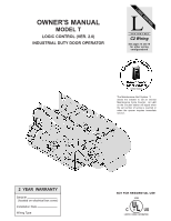
OWNER'S MANUAL
MODEL T
LOGIC CONTROL (VER. 2.0)
INDUSTRIAL DUTY DOOR OPERATOR
LOGIC CONTROL
L
C2 Wiring
FACTORY SET
See pages 15 and 16
for other wiring
configurations
Serial #
(located on electrical box cover)
Installation Date
Wiring Type
2 YEAR WARRANTY
The Maintenance Alert System
allows the installer to set an internal
Maintenance Cycle Counter. An LED
on the 3-button station will signal when
the set number of cycles is reached or
when the opener requires immediate
service.
TM
PATENT PENDING
NOT FOR RESIDENTIAL USE
LISTED
DOOR
OPERATOR
41B6